TIPs to insure the antenna is level
The moveable plate (with the boom) is designed to be offset from vertical. The boom is installed on the inside of the moveable plate to provide the down force to keep the plates together. The offset varies between 6-12 degrees depending on your ubolt, boom size and the tiltplate model. When installing a tiltplate there are several ways you can insure your antenna will be level in the operational position. Here are 3 methods you can use. Method 3 was offered by one of our customers, Dave / K8DH.
Your feedback on these instructions is welcome.
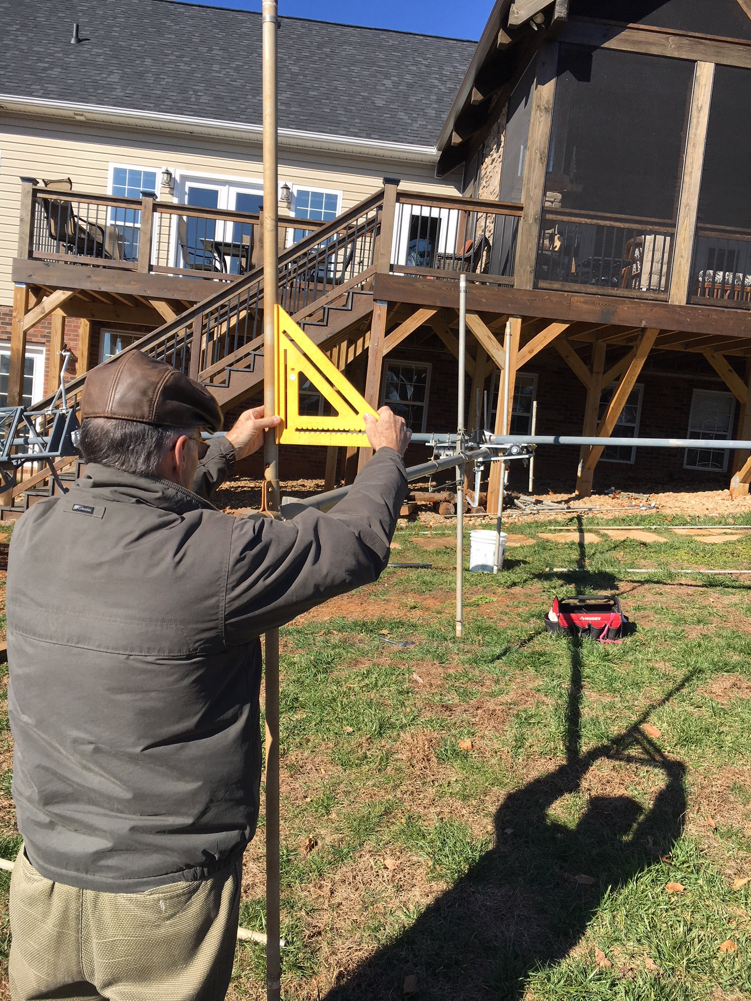
1) Protractor method
After your install the tiltplate on your tower, install a representative section
of your boom on the moveable plate. Manually close the plates together and
tie or clamp them together for the offset angle measurement. If you have
adjustable woodworking clamps, they work well. Use a protractor to get an
accurate offset measurement. Calculate the
element to plate angle as 90 minus the offset angle. Now install your antenna and
set the element to plate angle using the calculated
value.
![]() John / KD7UI built a jig
to assist in the process instead of using a protractor to do the alignment.
Click here to see John's document.
John / KD7UI built a jig
to assist in the process instead of using a protractor to do the alignment.
Click here to see John's document.
2) The "get it close and adjust as needed" method
Tilt the tower over to the maintenance position. Use the estimates below and install with the boom rotated so the elements closest to the tower make the angle noted below between the elements and the moveable plate. Same basic process as above but using estimates. Raise the tower and if the antenna is not perfectly level, tilt over and adjust as needed. This is an easy process if you have a motorized tilt or don't mind a few manual tilt cycles.
Boom Sizes, Element to plate angle
1 inch, 84 degrees
2 inch, 82 degrees
2.5 inch, 80 degrees
2.75 inch, 79 degrees
3 inch, 78 degrees
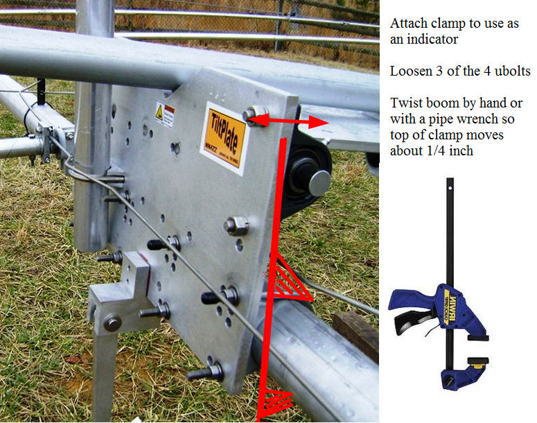
When making fnal adjustments, only a small amount of boom rotation is needed. Here is one way to make it easier to visualize the amount of adjustment needed. Use a woodworking clamp as an indicator. For example if the indicator tip is about 1 foot from the boom and it moves 1/4 inch, the tips of the element (at about 20 feet) will move about 6 inches.
3) The "Remove a Tube" method
This method is offered by Dave Head / K8DH for installing his 4 element Steppir.
Here is a summary of the steps David used, they are generally applicable to the
other SteppIR type antennas also. It can also be used
for OTHER types of antennas where the elements can be partialy installed. In
other words where only a section of the element can be installed rather than the
full length element. See notes and pictures below provided by
Dick / K0CAT.
A - Tilt the tower and use a carpenter's level to be sure it is level.
Make sure you measure it at the mast end, as some towers can be seen to droop
when horizontal.
B - Remove the 4 fiberglass tubes on the antenna on the opposite side from the
tower. Don't forget to first "Home" the elements inside the tubes. The antenna will be
resting on the 4 fiberglass tubes on the tower-side of the antenna. If you are
"building your steppir on the boom" then just insert 1 of the tubes on the tower
side to keep the weight down.
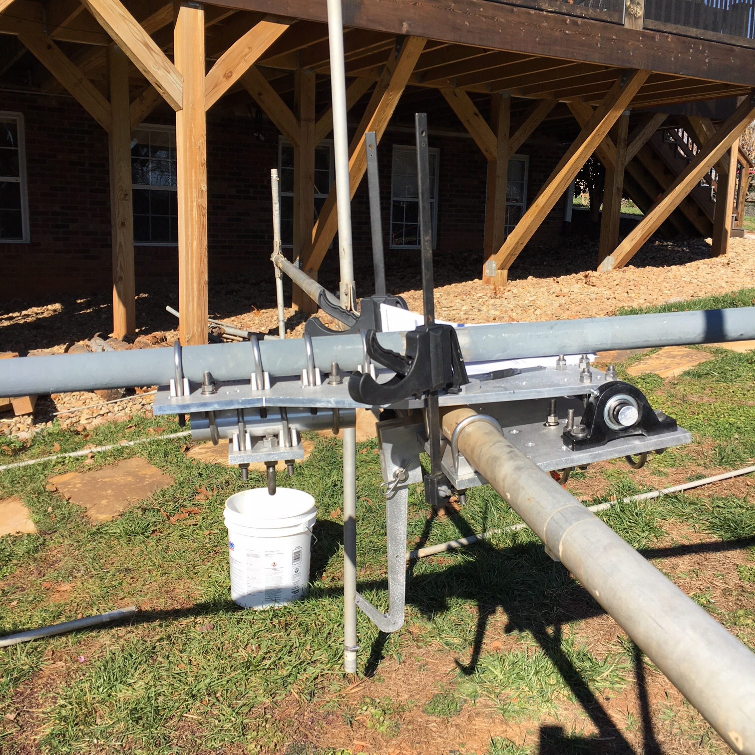
C - Now, using a a large rod or tube (e.g. a Radio Shack 5' mast), insert it on
the bottom end of the boom truss mast that is fixed to the moveable section of
the tiltplate. Using this as a lever, raise the element(s) of the SteppIR that
have been resting on the ground on the tower side of the antenna to a vertical
position. Make sure that the
tiltplate is completely folded closed, as far as it will go. Use a rope or other
fastening to clamp the two tiltplate sections together so that they are closed
as far as they can go (touching.)
D - Carefully loosen 3 of the 4 U-bolts holding the boom to the moveable part of
the tiltplate. Grab the 1st director of the 4 el. SteppIR which is very close to
the tower and tiltplate and, carefully loosening the remaining U-bolt, ensure
that the fiberglass tubes of the antenna are absolutely vertical. Again, the
carpenter's level can be used for this. Be careful so you don't lose control
and let the antenna can get away from you. Barely loosen that 4th U-bolt so the antenna
will move with some effort. When the element is vertical, tighten the 4th
U-bolt. Check it with the level, and adjust again if necessary. If you can
get some help with this step it is easier.
E - After getting the antenna elements vertical, its just a matter of tightening
all 4 of the U-bolts, put the fiberglass tubes back on and you are ready to
raise the tower back up.
Mark / WA2ILB has a
variation on this using the EHU mounting plate as the guide.
Click here to see his pictures.
![]() Dick
/ K0CAT used this variation with his Hy-gain LJ-205CA yagi.
Dick
/ K0CAT used this variation with his Hy-gain LJ-205CA yagi.
Here are his notes: