 Return to HOME page
 Return to Station Equipment page
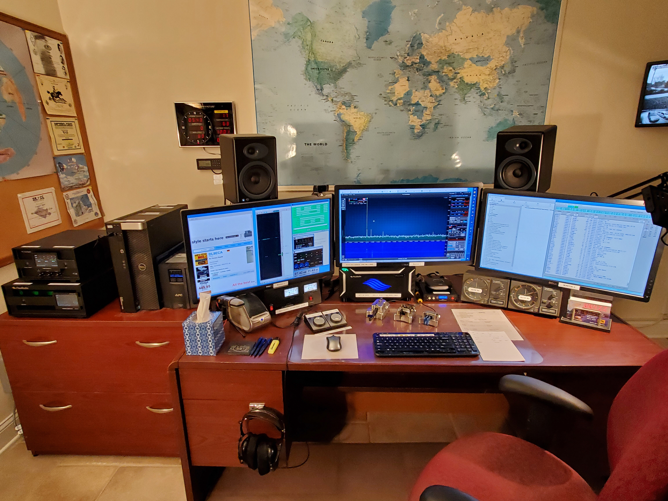
Left -- PGXL amp TGXL tuner
Center Back -- Flex 6600 and Bandmastyer 5
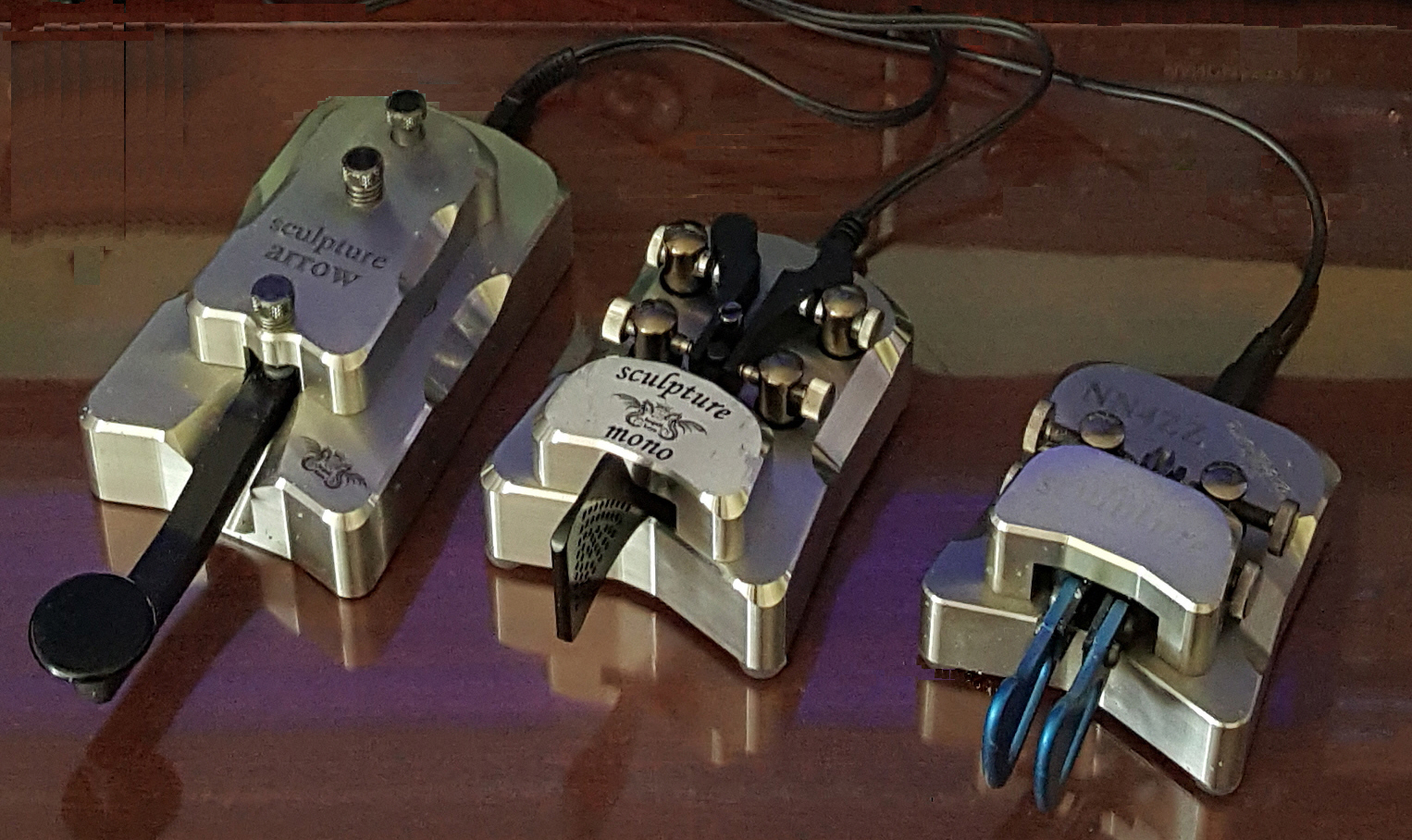
Center Front -- Two FlexControls, Begali
keys,
Right -- Yaesu G-2800DXA rotor controls.
Begali Arrow, Mono, & Sculpture keys...
Quick Links -- Some of these links are to my older 6700 page but are still
relevant.
Powered Speakers Audio Engine
5+ from 6700 page
Fiber Ethernet connection - RF and
Lightning mitigation NEW for 6600, PGXL and TGXL
Bandmaster V & Ratpack setup
- NEW for 6600
USB Port Protection - ESD, power surges and
lightning mitigation from 6700 page
RF Issues and Solutions - RF ground &
Common mode RF from 6700 page
Astron Power Supply -
NEW Adjust for 15 V
Voltage Troubleshooting - measurements, Low
voltage lockups
- NEW for 6600
6400 & 6600 Startup /
Shutdown procedure - Reset procedure - Error Codes
- NEW for 6600
Low Voltage Lockup issue and solution
from 6700 page
The FLEX Radio web page
CW Skimmer
and SDR-Bridge Setup and Troubleshooting notes
Data/NN4ZZ SDR-Bridge V3 & CwSkimmer V2 SETUP 1-Nov-2022.pdf
NEW Version 3
Setup for 2 Flex Control knobs - NEW on
6600 page
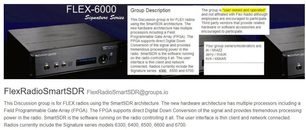
Click here or on the image
below to join the FlexRadioSmartSDR Groups.IO forum
Flex6600 & PGXL & TGXL order info
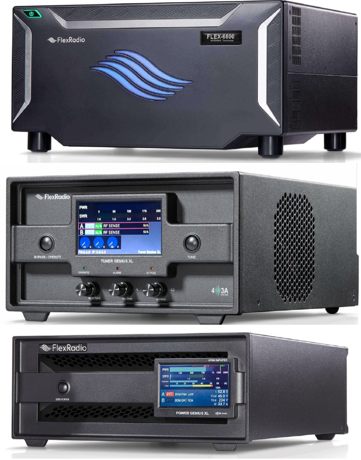
Flex 6600 ordered on: Oct 11, 2022
Received on: Oct 30, 2022 --- Serial Number4322-1104-5962
Flex TGXL ordered on: Oct 6, 2022
Received on: Oct 11, 2022 --- Serial Number 0663
Flex PGXL ordered on: Oct 7, 2022
Received on: Oct 11, 2022, replaced on Nov 10, 2022 --- Serial
Number 8-360 / 22-0040
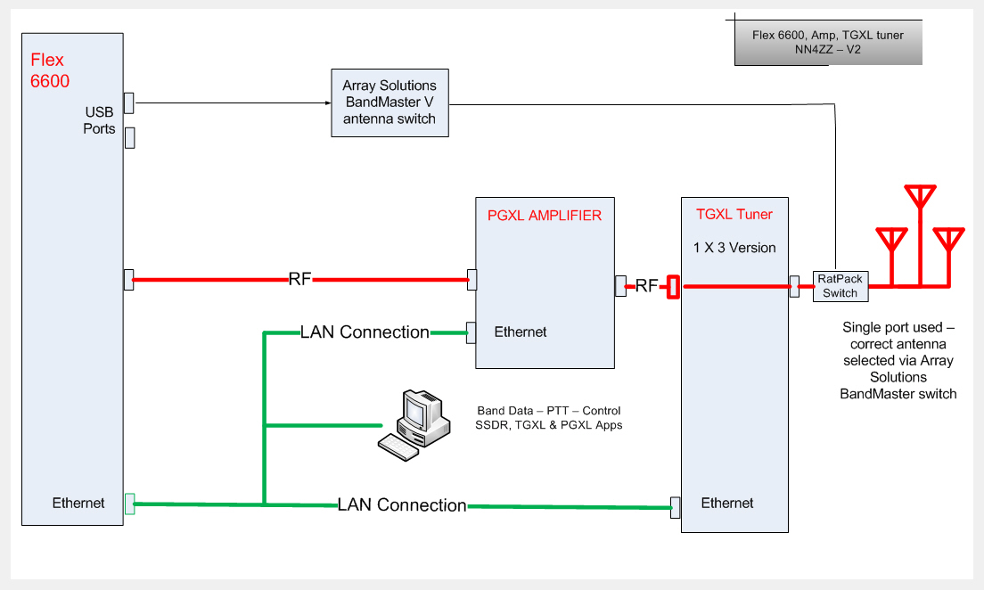
Station equipment overview
-- File: Flex Radio / Flex 6600 Station Diagram V1.jpg
Ethernet and Fiber
link for the 6600, PGXL and TGXL
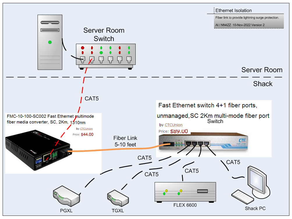
The Ethernet port on the Flex Radio is a
potential weak point for lightning surges. For protection I added a fiber
link to electrically isolate the port.
The problem is long runs of CAT5 cable
act link an antenna and a close by lightning strike will induce a voltage spike
in the cable. The solution is to isolate the devices you want to protect
with a short fiber link near the device. In addition a close by lightning
strike can induce spikes into any of the wiring systems (phone, power, cable TV
coax, etc) in your house which can jump to your ethernet CAT5 cable.
The install was plug and play and took about 5 minutes.
The cost was about $150.
Replacing an ethernet interface card in a PC is easy, if the ethernet interface
card in your radio is damaged, it will require a trip back to Texas for repairs.
Click here or on the image
below to join the FlexRadioSmartSDR Groups.IO forum

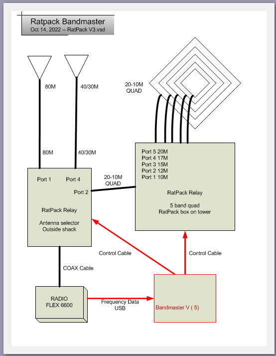
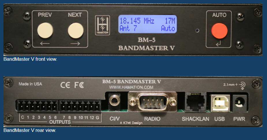
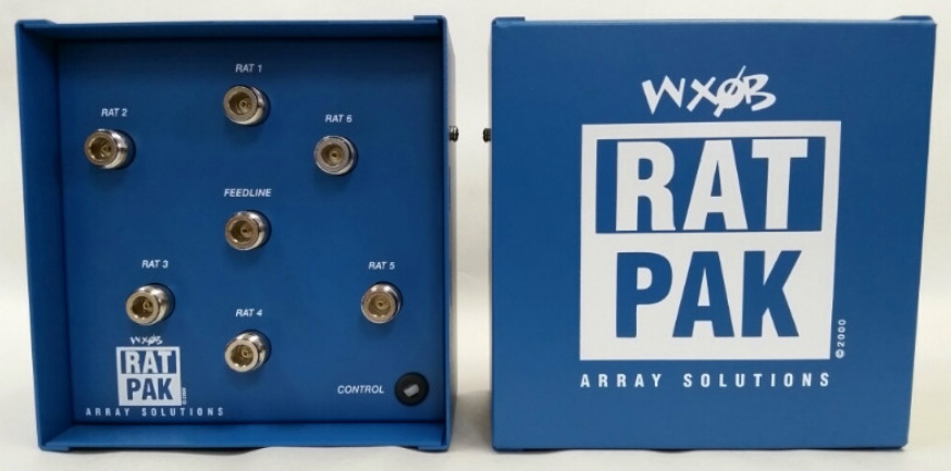
Ratpack Bandmaster
V Antenna selector
The Bandmaster 5 is connected to the Flex 6600 via USB to get
band data.
The Bandmaster then connects the RatPack relays for 80-10 meter
antennas.
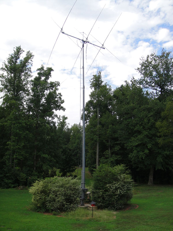
Antennas and Towers
Click the PICTURE to go to my Antenna and Towers page
CrankupTiltoverTowers -- A
forum on Groups.io dedicated to
crankup and tiltover towers. You may be interested in joining. Click
here to vist the forum

FlexControl setup to use 2 knobs with SSDR
There are several ways to setup the
software to use 2 (or more) Controls. Since I always have SDR-Bridge
running I use it to control one knob and SSDR to control the other one.
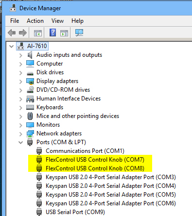
- To start verify that Windows device Manager shows 2
FlexControls
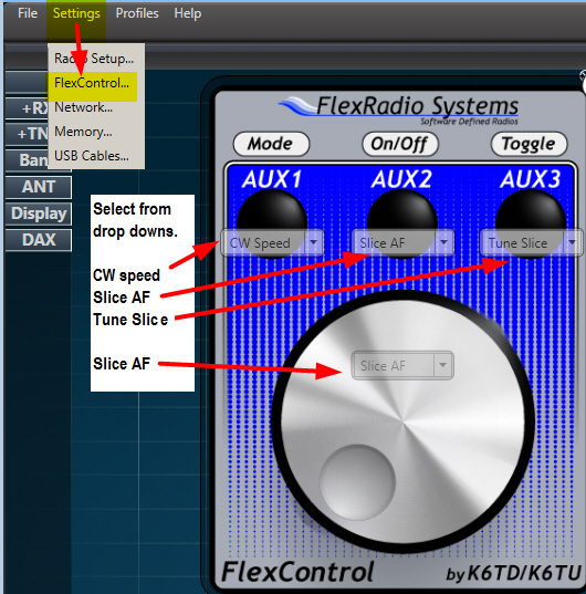
- Start up SSDR and it will grab one of the FlexControls
- Configure it for the functions you want, I have mine set to control the
CW Speed, Slice Volume, and Tuning for the active slice. You could have
another function for the Knob press, but I just have it also set for the
Slice volume.
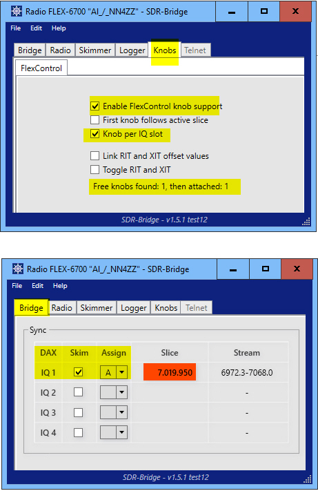
- Now start up SDR-Bridge and configure
as below, it will then find and grab the other FlexControl knob.
- Note the message that says ďflex knobs
found 1, then attached 1.Ē
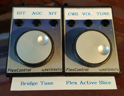
I put some Dymo stickers on the FlexControl to remind me of
the settings.
I leave the PC up 24x7 and also leave
the SDR-Bridge program running on my PC 24x7. I do shut down SSDR when the
radio is not in use. The setup sticks and I donít have to go back and do
anything when I start up SSDR. The FlexControl knobs stay properly configured.
If you shut down your PC regularly, The only thing you have to do is start SSDR
first to let it grab itís knob and then start SDR-Bridge to grab the other one.
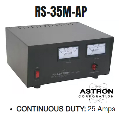
Astron Power Supply - Voltage measurements and
troubleshooting
Power
Cabling --
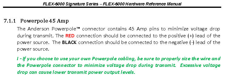
Flex uses a 45 amp Powerpole connector. If
you make your own power cables be
sure to use 10 gauge wire and
the 45 AMP contacts to minimise voltage drop. ( not the more
common and lower rated 15-30 amp contracts). From the hardware manual:
This grease is recommended to use on the power pole connectors and the
internal fuse. It will prevent voltage drop issues.
Use a very, very small amount, it spreads.

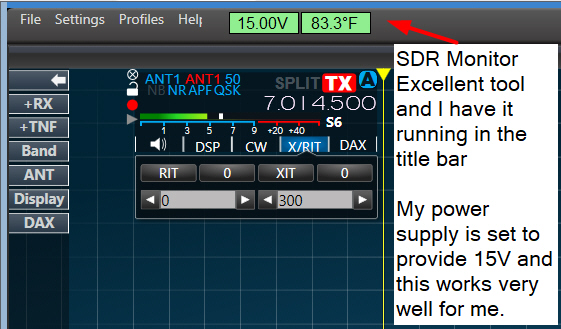
The power supply is adjusted to provide 15V -
within the range specificed by Flex
The steps to adjust the Astron RS-35M supply voltage are in this document by W1MIK.
http://www.repeater-builder.com/astron/voltage-adjust/voltage-adjust.html
Or CLICK for
PDF
Here is a good utility to monitor the voltage on the Flex Radio
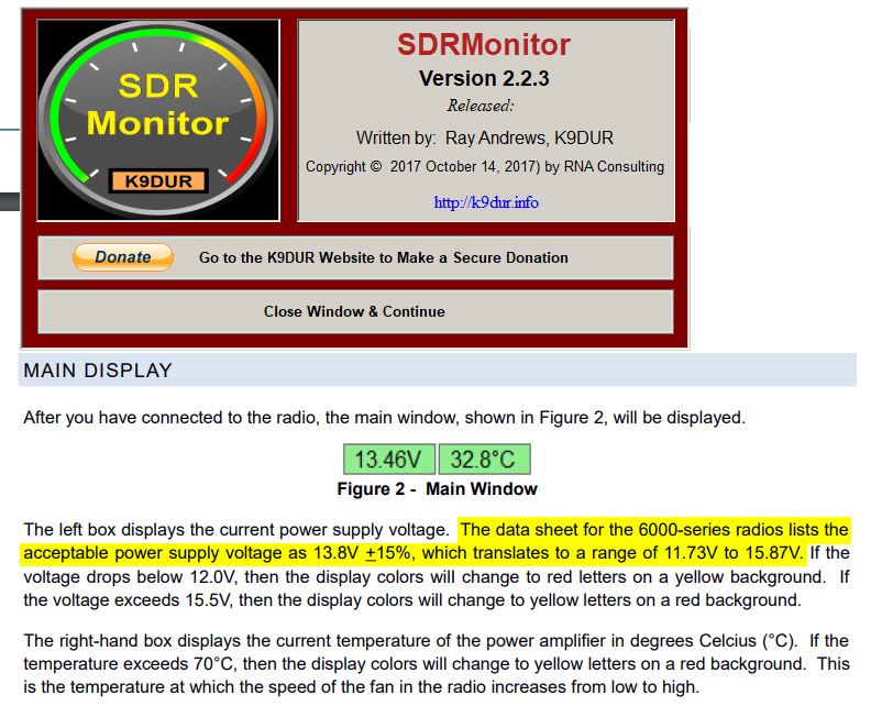
The Voltage and Temp display ( the Green box shown above) can
be dragged to reside on the SSDR app.

SDRMonitor is available here:
https://k9dur.us/smartsdr_utilities.php
I recently changed radios from a 6700 to a 6600. There
were some voltage drop issues on the 6700 that I described in detail, see link
below.
There is a big difference with my 6600. The internal volteage
drop is very low on the 6600 as measured internally by SDRMonitor when
transmitting at 100W.
The total drop is only about 1/3 of what it was on
the 6700.
Below are the new measurements for RX and TX at 100W. The
voltage supplied to the radio is measured with a Fluke 177 meter at the power
supply
and at the powerpoles on the back of the radio while they are plugged
into the radio. The internal voltage is reported by the SDRMonitor app.
NOTE: to accurately
assess a voltage issue you need to measure the voltage in 3 places. The
power supply terminals, the power pole terminals, and internally with a utility
like SDRMonitor. It is also important to measure all 3 places in both RX
and TX. This will help your determine whether the problem is the power
supply, the power cable, the power pole connectors at the radio or in the radio
internally at the fuse or other area.
RX readings
-----------------
1 - The voltage at the power supply is 15.13 volts
2- There is a measurement of 15.10 volts at the power poles on the radio. A
drop of 0.03 due to the power cable resistance.
3 - There is a measurement of 15.0 volts internally by SDRMonitor - an
additional drop of 0.1 volts internally ( radio fuse, wiring, etc)
TX readings, key down 100W
-----------------------------------------
1 - The voltage at the power supply drops very slightly to
15.11 volts, a drop of 0.02 volts
2 - There is a measurement of 14.77 volts at the power poles
on the radio - this is a drop of 0.34 volts at the power pole due to the
resistance of the power cable from the supply to the radio when supplying about
15 amps
3 - There is a measurement of 14.74 volts internally by
SDRMonitor - this is an additional drop of ONLY 0.03 volts internally ( radio
fuse, etc) for a total of 0.26 volts.
Here is the seup used to measure the voltage at the radio.
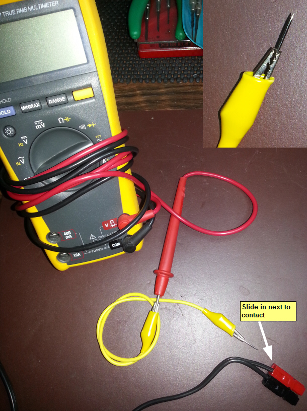
For more information about my 6700 LOW Voltage lockup
issue and solution,
see this link on my 6700 page:
Low Voltage Lockup issue and solution
from 6700 page
6400 &
6600 Startup and Shutdown, NON-M models
These notes are for users
that shut off the power to the radio when it is not being used.
If the 12V power
is always on, there are no special requirements - just hit the radio button (for
either OFF or ON) and forget it. Expect to wait several seconds until the panel
indicates on if starting up.
Startup -- apply power, wait a few seconds
then press the power control button as noted below.
Shutdown - press the button and wait till it finishes
before shutting off the power supply as noted below.
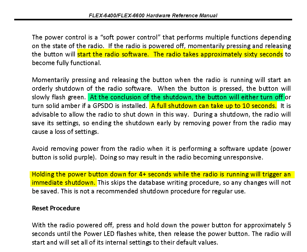
The Correct Power Up and Power Down Sequence for "M" Model Radios
The
M model radios have an additional set of processors that interface the
front panel with the radio RF section and these processors need
sufficient time to initialize and shut down to ensure the proper
operation of the radio. When using an "M" model radio, it is
important that the radio is allowed to shut down completely before
turning off the 13.8 VDC power supply. Failure to do so may result
in the radio not completely saving the operating state information which
may prevent the radio from not starting up properly.
When powering down
an M model radio, do the following:
- Power down by pressing and releasing the
radio's power button once.
- Wait for the radio to
fully power down. Once the screen goes blank, the power button will stop
flashing green and you will hear the last relay click.
- Wait about 45 seconds for
the remaining internal processors to shut down, then turn off the power
supply (if this is something you normally do - it is not, however,
necessary. Leaving the power supply on will speed up the boot-up time).
When powering up an
M model radio, do the following:
- If the DC power supply is
off, turn on the 13.8 VDC power supply to the M model radio, otherwise, skip
to the 4th bullet to start the boot-up process.
-
Wait for 2
minutes (120 seconds) before powering on the radio to provide time
for the front panel to initialize
- Press and release the power button once
to start the radio boot-up process.
- Wait for the radio to boot
up completely (do not press the radio's power button again). The power
button will flash green before turning solid green (unless there is a GPSDO
installed where the LED may be amber or blue (solid or flashing). The power
button should not show a different color than green, amber, or blue.
More here:
M model Power up / down article on the help desk
****
Error Codes ****
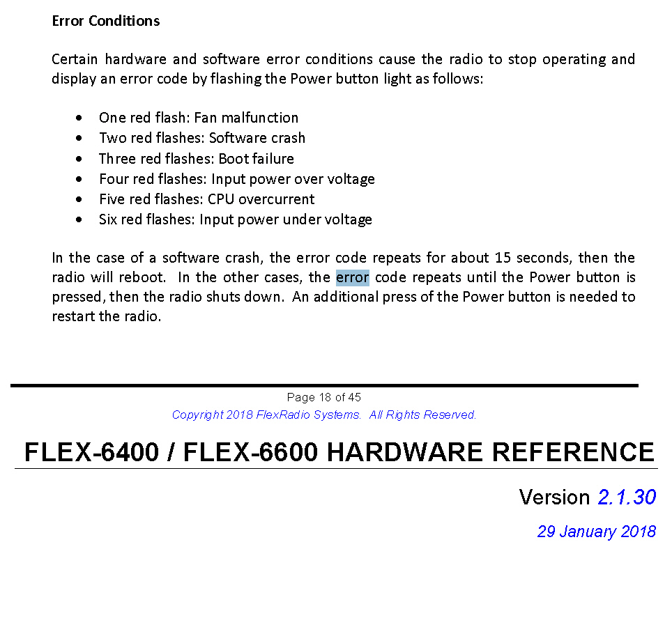
Resolving the "single red blink" Fan Error on Start Up
The FLEX-6000 has the ability to detect a variety of faults that could
potentially harm the radio and one of these is detecting if the cooling fan is
working properly. When booting up your radio, if the cooling fan is not
spinning fast enough to provide adequate airflow to cool the PA, CPU, FPGA, and
SCU(s), the PSoC will report the error which results in the radio firmware
shutting down and the power button blinking red once and then repeating.
This fault can be a problem with the fan itself or the fan controller.
However, there is a particular condition that may result
in a false positive error indication.
If the radio experiences a momentary loss of DC power for less than 30 seconds
and then power is reapplied to the radio, this results in a partial reset of the
radio's internal processors leading to a condition where the fan controller is
not providing adequate voltage to the fan.
If you experience a fan error on startup, the first thing you want to do is a
"cold boot" of the radio to reset all of the radio's processors.
The following procedure will "cold boot" the radio:
NOTE: If
you have a cable connected to the REM ON connector, please remove it before
running the reset procedure. Reconnect it once the procedure has been
completed.
- Power off the radio by
pressing and releasing the power button. Allow it to completely power down
before continuing by waiting for the power LED to turn off (or amber if a
GPSDO is installed). If pressing and releasing the power button does not
shut down the radio, press
and hold the power button until the radio shuts down.
- Once the radio is powered off, wait
for 2 minutes to allow for all processors to properly
shut down.
- Remove the power cable
from the radio for at
least 30 seconds and then reconnect it. It is
important to remove the power cable from the radio and not just turn off the
power supply.
- After reconnecting the DC power cable, wait
for 2 minutes to allow for the internal PSoC processor
to boot up completely before continuing.
- Press the power button to restart the
radio.
If you continue to receive a fan error after running the cold boot procedure,
please open a HelpDesk
support ticket so that one of our support engineers can triage
the issue.


