 Return to FAQs page

TIPs to install
a PRO67
The Mosley PRO67B and 67C have two driven elements connected by phasing
tubes. Here are some tips for installing and leveling the elements if you
are building the antenna on the TiltPlate. There are also pictures and tips
for installing the phasing tubes.
Building the antenna on the TiltPlate and some leveling tips.
- Install the TiltPlate on the tower which is tilted over in the
maintenance position (close to horizontal)
- The boom plate will be hanging down
- Install the boom on the boom plate of the TiltPlate
- Close the plates and clamp them together. This is the position the
plates and boom will be in when operational
- Install the 2 driven element mounting bars. The bars are mounted
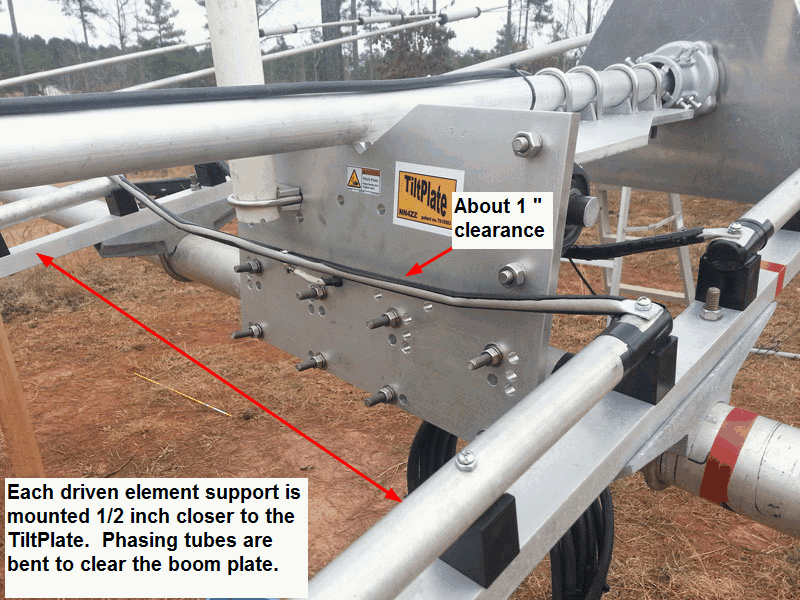
1/2 inch closer to the TiltPlate than normal See the diagram below. .
This is to accommodate the phasing tube location per Mosley. (note they
don't recommend using longer phasing tubes)
Don't mount the phasing tubes at this time.
The driven element mounting bars should be pointing
roughly vertical. There should be exactly 90 degrees between the
mounting bars and the mast plate.
- If you are installing a KARLock this is also the time to check the
adjustment for the catch plate.
- Release the clamps and let the boom plate swing back down.
- Attach the phasing tubes and swing boom plate back up to insure there is
no interference. See notes below on the phasing tubes
- Attach the driven elements to the mounting bars
- Optional - raise the tower and verify the elements are level.
- Using the driven elements as a guide, mount the other
elements
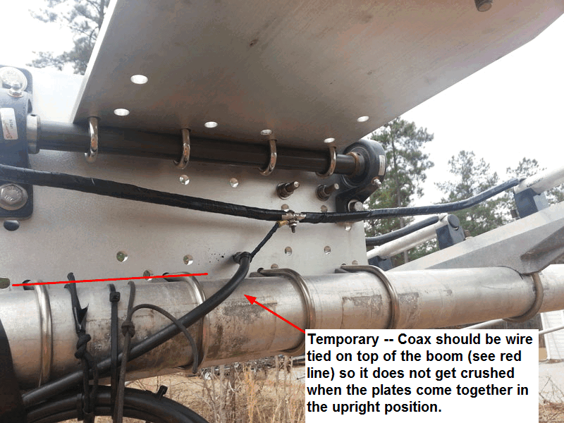
- Install the coax and other wiring.
Adjusting and Installing the phasing tubes.
- You can either adjust (re-bend) the supplied phasing tubes or make new
ones. See material and tool suggestions below.
Please note: Although I made a set for test
purposes, I don't sell or provide phasing tubes. The notes below are
provided in case you would like to make a set.
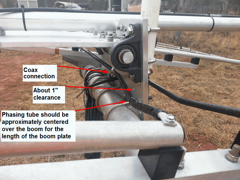
- The phasing tubes must be bent to locate them approximately over
the boom. The inside tube is rotated in toward the boom plate to
provide about 1" of clearance. (see diagram)
- The TiltPlate may be centered between the driven elements or it may be
offset to one side. This location will determine the bend
pattern of the phasing tubes. A diagram and picture below shows the
bend patterns for both.
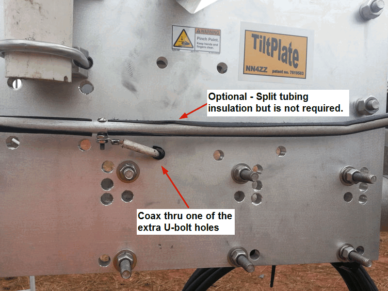
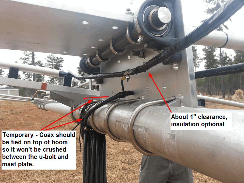
- The center coax conduction may be run through one of the extra u-bolt
holes (see WF4W picture for example on the 67C)
- The phasing tubes should be about 1" away from the plate on the front
and back
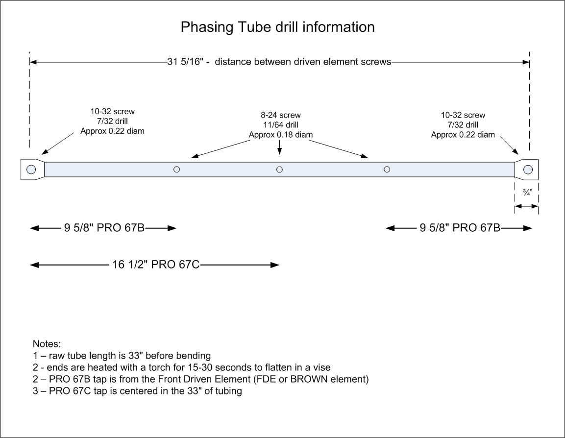
Diagrams for making or bending the phasing tubes.
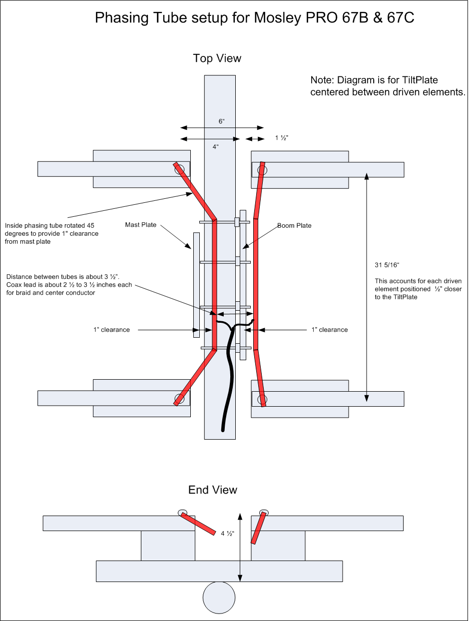
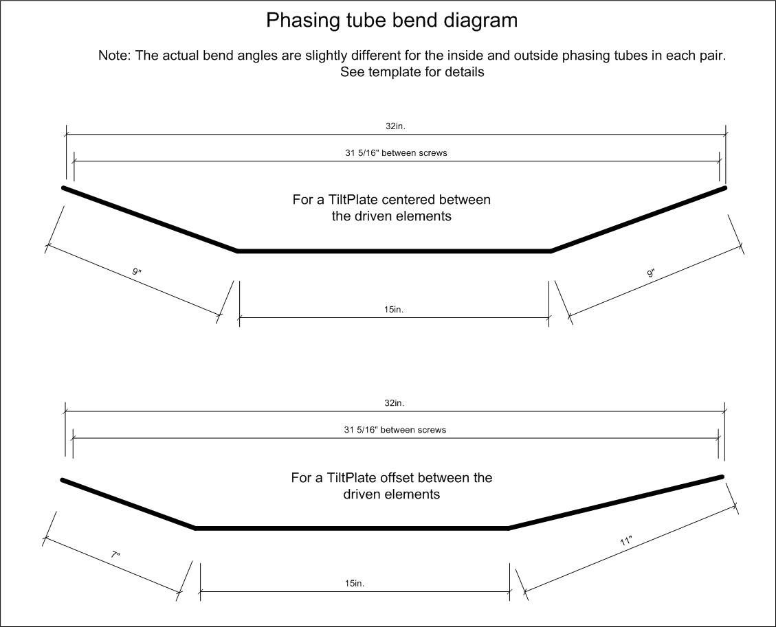
NOTE: The diagram below shows coax taps for both the 67B and 67C. On
the 67B taps are shown from either end although you only need one hole.
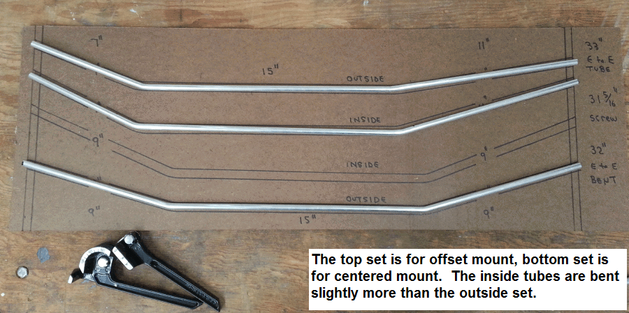
This pictures shows 3 sets of tubes for various plate locations. The
top 2 sets are for the offset mount. The bottom set is for a center mount.
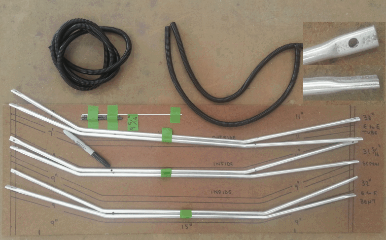
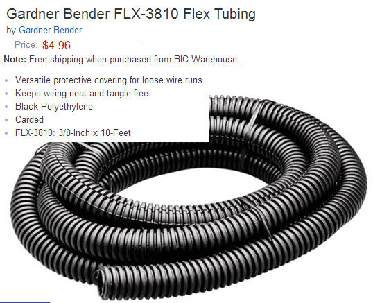
24 inches of split tube insulation may be used if desired on the inside
phasing tube
Tool and Supplies
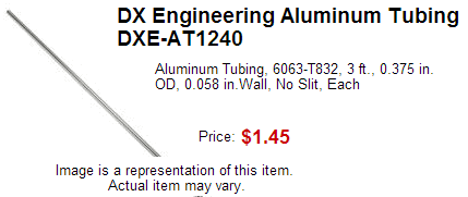
Mosley recommends using 0.058 wall tubing which can be purchased from DX
Engineering.
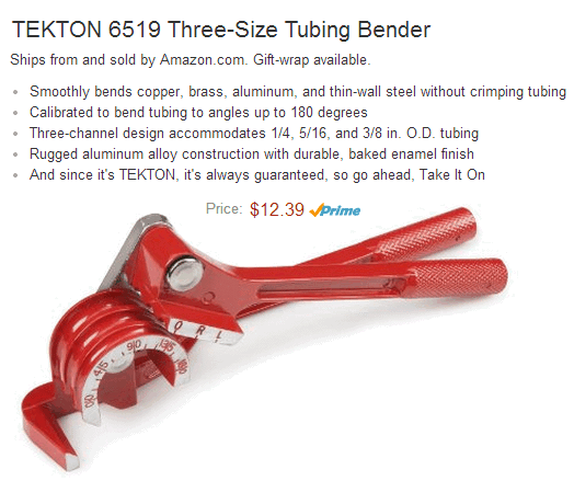
A tube bending tool is require, here is one example...
Split flex tubing can be used if desired. Home Depot, Amazon, etc carry
it.
WF4W Installation
The pictures below are from the tower and Mosley PRO67 project by
Tad / WF4W. Tad is local in the Atlanta area and invited me to
take the pictures so I could share with other Mosley Pro 67 users.
Tad used the supplied phasing tubes and rebent them to fit. Note,
the 67C coax tap is in the center of the phasing tubes.
