![]() Return to TiltPlate page
Return to TiltPlate page
![]() Return to FAQs page
Return to FAQs page
Lateral boom flexing issue and Boom truss options
The booms on some of the larger SteppIR Antennas such as the DreamBeam36, DreamBeam42 or MonstIR exhibit excessive lateral bending when raising the tower or in a heavy wind. This can also be a problem on the 4el Steppir with the 40/30 loop option. If the lateral bending is sufficient, it can cause the antenna to lift. Steve / W4QMC noticed his DreamBeam36 boom would flex laterally in a light breeze. This was causing the TiltPlate to lift and engage the KARLock.
SteppIR now offers a T-Bar truss solution to address the problem. The new T-BAR truss is standard on the DB42 and available as an option on the DB36. It can also be ordered to retrofit on the older antennas. There are also several other "lateral truss" support options that are described in detail further down the page. You may want to consider adding one of the lateral support truss options in addition to the SteppIR supplied T-Bar for additional lateral support especially on the DB42. Here are the pricing details for adding the T-Bar option of one of the other SteppIR models. Thanks to Adam at SteppIR for this Information.
Option on the DB36 -- $383.10
Option to retrofit to the 4el SteppIR - about $385
Option to retrofit an older MonstIR - about $475
Note, with the new truss, the stackable configuration to extend the mast above the TiltPlate is not supported. The rear set of truss cables will interfere with the main mast.
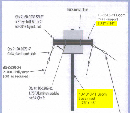
T-Bar truss mast is 4' feet long and 1.75" in diameter and attached to the TiltPlate with 2" u-bolts that are provided.
The diagram below is from the DB42 manual. When used on smaller antennas the "truss mast plate" can be mounted lower on the truss mast. For example the truss mast plate for a 4el SteppIR can be mounted at 30" - 36" above the boom leaving some of the mast extending above the truss mast plate. A small 2M vertical could be attached for example.
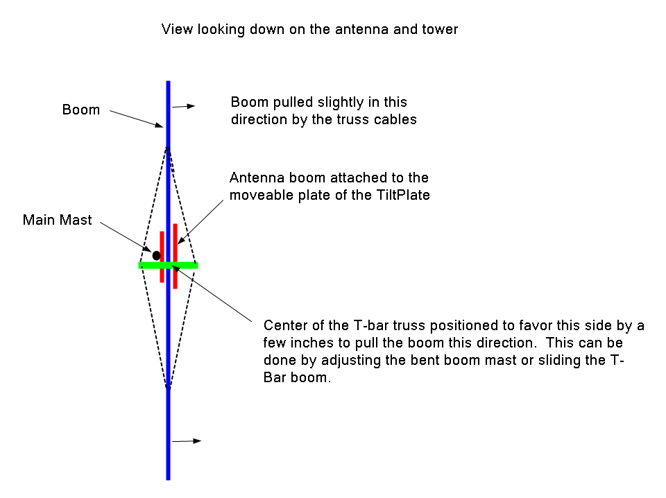
When installing and adjusting the T-Bar strut insure that the boom plate side of the boom is favored. This is controlled by the vertical position of the top of the T-Bar truss over the boom and the cable tension adjustment. . Adjust for a slight bend of the boom in the direction shown in the diagram below. On the T-Bar truss you can also slide the "boom truss support tube" a few inches towards the boom plate side to assist in getting this adjustment.
When installing the T-Bar truss there are several options to make the boom truss mast as vertical as possible. The setup depends on the antenna boom diameter and height of the "truss mast plate." For example on the DB42 the plate is at 48 inches, and on the 4el SteppIR it is around 36 inches. Here are some options:
The upper u-Bolt on the TiltPlate will be come with a shim under it. You can remove the saddle from the lower u-Bolt to get additional adjustment.
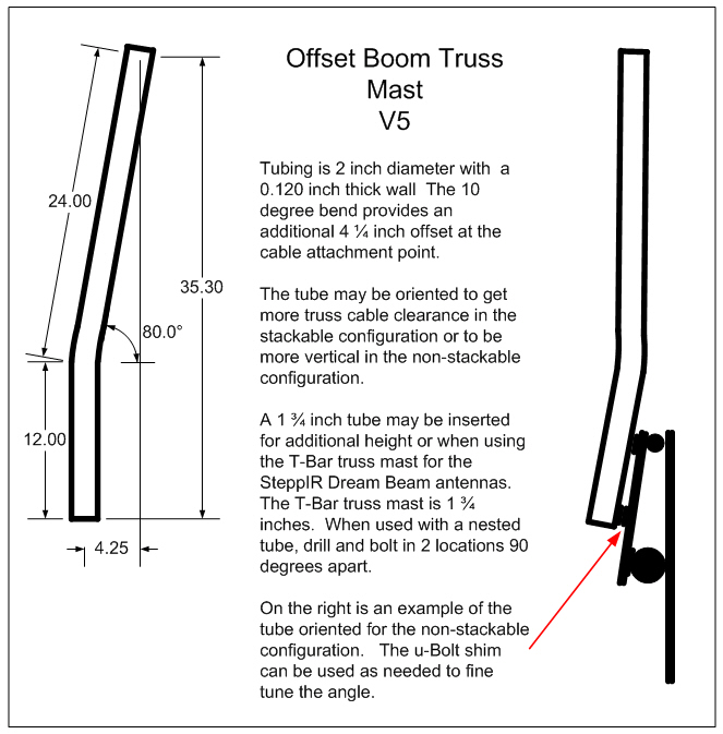
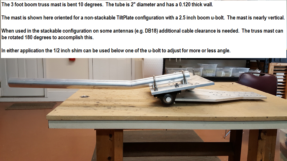
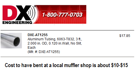
Have the boom truss mast bent about 10 degrees. On the 4 foot T-bar truss mast a 10 degree bend will provide about 6 inches of offset at the 4 foot mark. You may find the u-bolt shim is no longer needed or can be used on the other u-bolt. A local muffler shop can do this for about $10-$15.
Install a pre-bent 2" truss mast as shown in the diagram below and then nest the T-Bar 1 3/4 inch mast into the 2 inch mast. Mount the "truss mast plate" as needed on the 1 3/4 inch mast to be the proper height above the antenna boom. You may find the u-bolt shim is no longer needed or can be used on the other u-bolt. You can make your own or I sell one that is prebent, see the main page for price. See diagram below.
It is not critical for the mast to be perfectly vertical but it helps with the boom flex adjustment mentioned above. You can also mount a small UHF antenna on the boom truss mast and it helps to be as vertical as possible in this case.
INSTALLATION --
During the initial installation process you can set up the boom truss mast after
mounting the TiltPlate and SteppIR boom but before adding any of the elements.
Manually close and clamp the plates together and install the boom truss mast.
Make any necessary adjustments to the u-bolts and shim to align the boom truss
mast with the main mast so it will be as close as possible to vertical. It is
not necessary to have the boom truss mast perfectly vertical. But if you
can't get the alignment as good as you would like, consider the bent boom
truss options above.
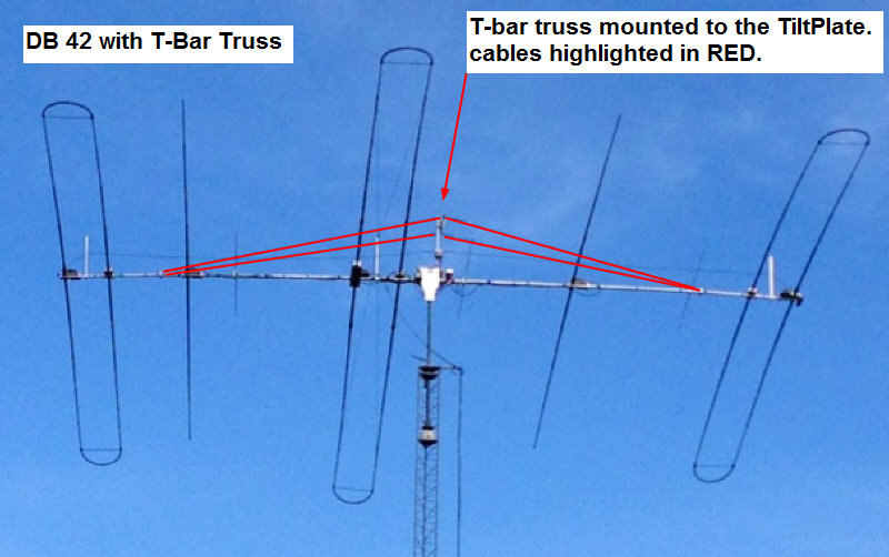
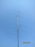
Example of a DB42 with the T-Bar truss installed.
Even with a lateral strut support or the new SteppIR T-Boom truss, a KARLock is HIGHLY recommended on the DB36 & DB42 and any of the heavy "loop" element antennas due to some residual lateral flexing of the boom. This is to prevent the boom from flexing or bowing excessively in a high wind when it lifts. The excessive bowing may prevent the antenna from returning to the normal position when the wind subsides. The KARLock will help prevent this from occurring.
More Solution Options
Option 1 is a single lateral strut added to the TiltPlate that is described below.
Option 2 is a bilateral support. Option #2 provides additional advantages and is documented further down the page.
Option 3 is a parallel boom to reduce flexing
Option 1 - Add a lateral truss mast support that mounts directly to the TiltPlate. This option can be used alone or in conjunction with the T-Bar truss. This modification only provides support in one direction but solves the lifting problem. You can make it yourself or I'll provide one for my cost which is $123. See parts list, diagrams and price information below. You will need to add your own 3 foot truss mast and cables. The cables attach to the boom at or near where the vertical truss cables attach. Email for more info and ordering.
NOTE: One advantage of the lateral truss option is that you can use the STACKABLE option if desired and is you are NOT using the T-Bar truss. This allows the mast to extend above the TiltPlate to mount another antenna like a 6M or 2M yagi in the main mast. Since there is only a single additonal cable added to the front of the TiltPlate and the original single boom truss cable is kept, there is no interference when tilting the tower over. As noted above, the STACKABLE option is NOT supported when using the T-Bar truss.
Comment from Steve/W4QMC - "...this mod DOES solve the problem conclusively !
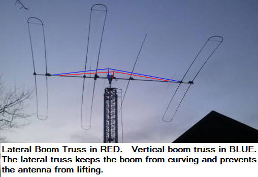
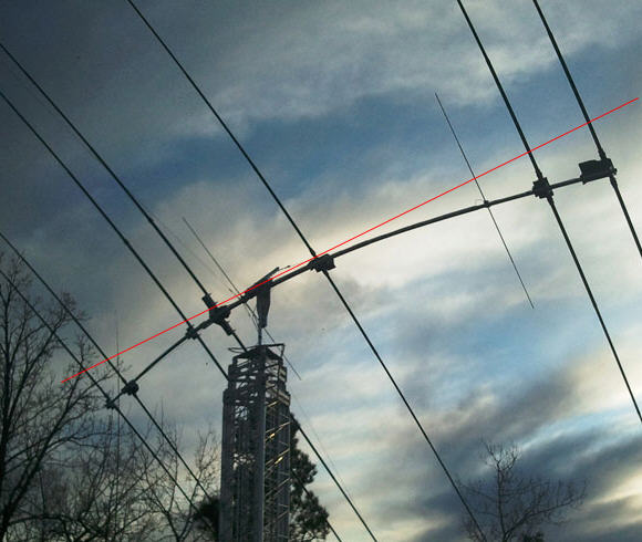
Jeff / W0JM built his own strut using the design and has some good before and after pictures on the customer page. Click here to see more Jeff's installation. Below is a closeup showing the lateral strut installed with the cables outlined in RED.
This picture shows Jeff's antenna BEFORE the lateral strut was added. The RED line helps to show how the boom is bending. This shifts the weight and causes the TiltPlate to lift.
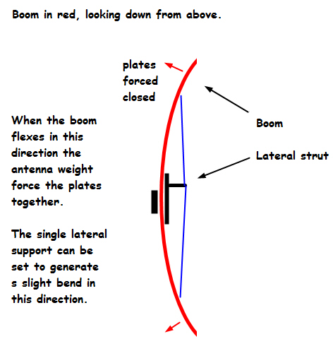
A slight bend in the boom in the direction shown below is needed to prevent lifting. In this diagram for the lateral strut, the bend is exaggerated for illustration purposes.
The truss support bracket mounts over the u-bolts. The model shown above is for the 2.5 inch u-bolts on the DreamBeam 36. The tube shown above is just for illustration. You need to provide a 3-4 foot 2" tube for the actual installation.
The model shown above is for the 2.5 inch u-bolts on the DreamBeam 36. The tube shown above is just for illustration. You would need to provide a 3-4 foot 2" tube for the actual installation.
The model shown above is for the 2.5 inch u-bolts on the DreamBeam 36.

The model shown above is for the 2.5 inch u-bolts on the DreamBeam 36 or 4EL SteppIR
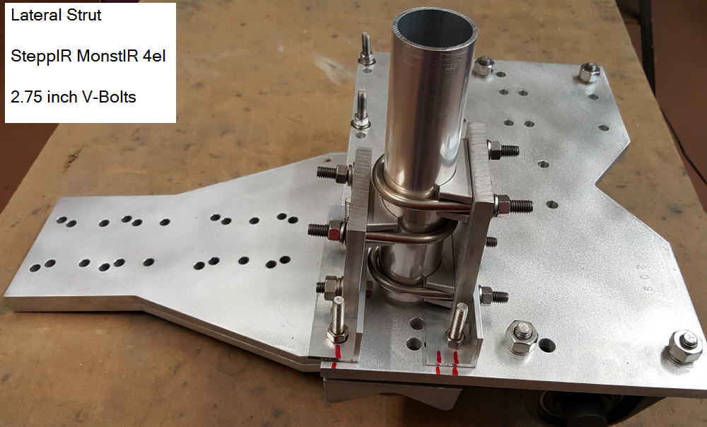
The MonstIR model uses the same parts in a different configuration.
The model is for the 2.75 inch V-bolts on the MonstIR.
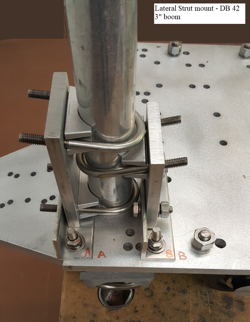
The truss support bracket mounts over the u-bolts. The model shown above is for the 3.0 inch u-bolts on the DreamBeam 42. The tube shown above is just for illustration. You need to provide a 3-4 foot 2" tube for the actual installation.
Lateral strut setup for antennas with a 2 inch boom
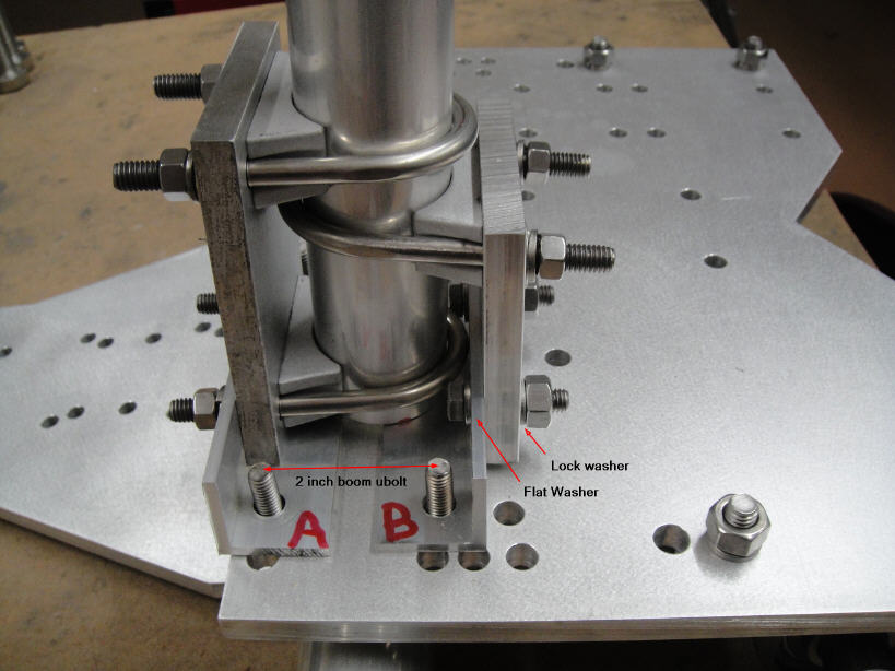
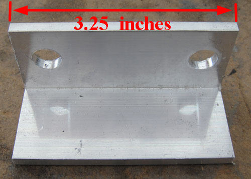
MonstIR spacer plate - the 7/16 inch drills match the spacing on brackets for the 2 inch u-bolts (2.40 inch center to center)
2 inch U-bolts, DXE-SAD-200B from DX Engineering
Approximate Cost for Materials
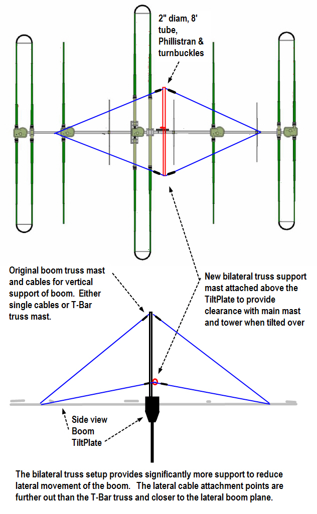
Option 2 - Add a bilateral boom strut
Use a plate mounted to the boom truss mast to provide a lower and longer tube to provide lateral support in both directions. The bilateral support offer a number of advantages.
Provides lateral support in both directions
Reduces boom stress/fatigue from flexing
Stabilizes the antenna and prevents additional flexing when tilting the tower over to prevent the elements from contacting the ground as soon.
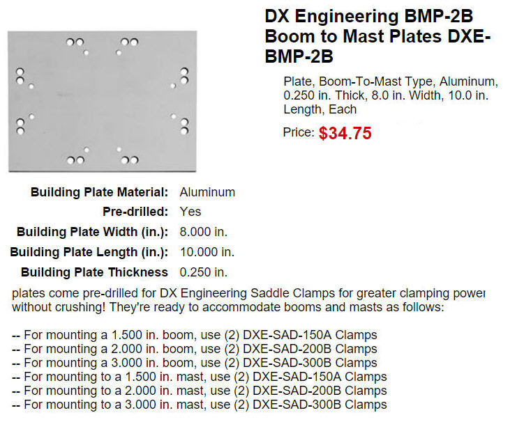
Mount the plate close to the top of the TiltPlate but high enough to avoid any interference with your main mast or tower when it is tilted over. Depending on your tower and mast setup this may only be a few inches above the TiltPlate. You may also be able to use the original boom/mast plate that came with your steppIR antenna.
Mount the tube to the plate so that it is parallel with the antenna elements. The tube should be 6-8 feet long and you may want to use a fiberglass tube to avoid interaction with the elements electrically.
Attach the cables to the end of the tube and out to the boom on each side where the vertical boom truss cables are attached.
Credits: This idea was presented to me by Bill / W7EXG who passed it on from Larry W7LB. Both are planning to implement a version of this and I'll add pictures and notes as they become available. For the reasons listed above, I believe this is a very worthwhile addtion for anyone with a DB42 (even if you don't have a TiltPlate) and want to thank both Bill and Larry for their input.
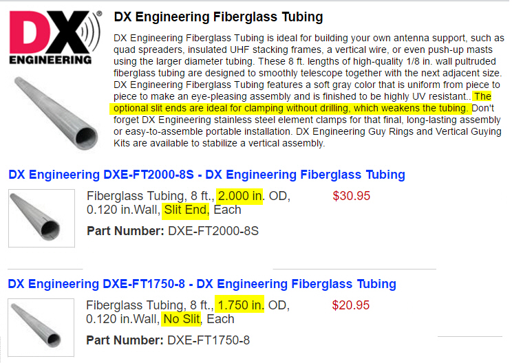
Here are some suggestions for materials from DX Engineering. For the tube use a 2" fiberglass tube with a 1.75" tube fully nested for additional strength. Either use clamps or drill to attach the turnbuckles. The 2" tube is available with or without the end slits depending on your method of attaching the turnbuckles. If you use clamps, then also add one on each end of the slitted 2" tube to clamp the 1.75" tube in place. If you drill thru the tubes to attach the turnbuckles then you can just order a 2" tube without slits.
Option 3 - Add a parallel boom
Biel / EA6DX developed a another method to reduce boom flexing. His method is to add a tube parallel to the boom. His application is not on a TiltPlate but could be adapted by swiveling the tube up and horizontally parallel with the boom.

Here is a link to a short video showing the DB36 in 86 km/hr winds.
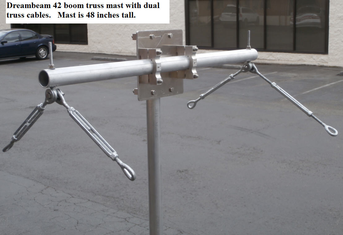
Stackable option - K9CT dual T-Bar
Craig / K9CT has a DB42 stack on his fixed tower. Craig developed a dual T-Bar boom truss to enable him to do this. His idea can be used with the TiltPlate if you want to use the stackable configuration. This would allow the main mast extend above the TiltPlate and install a 2M yagi or other antenna. Craig is using a ring rotator on his fixed tower and acquired most of the parts for the dual T-Bar from K0XG http://www.k0xg.com/home/. SteppIR or DX Engineering may also be a good source for the parts.
Here are some pictures showing the setup.
Note the turnbuckle between the T-Bars. The plate on the boom between the T-Bars is for attaching to Craig's ring rotator. This is where the TiltPlate would mount. Using Craig's setup, the turnbuck should be set up to be behind the main mast to allow the TiltPlate to tilt as the tower is lowered.
Click here for more pictures of Craig's setup
Click here to see a video of his setup.