![]() Return to HOME page
Return to HOME page
![]() Return to Station Equipment page
Return to Station Equipment page
Quick Links
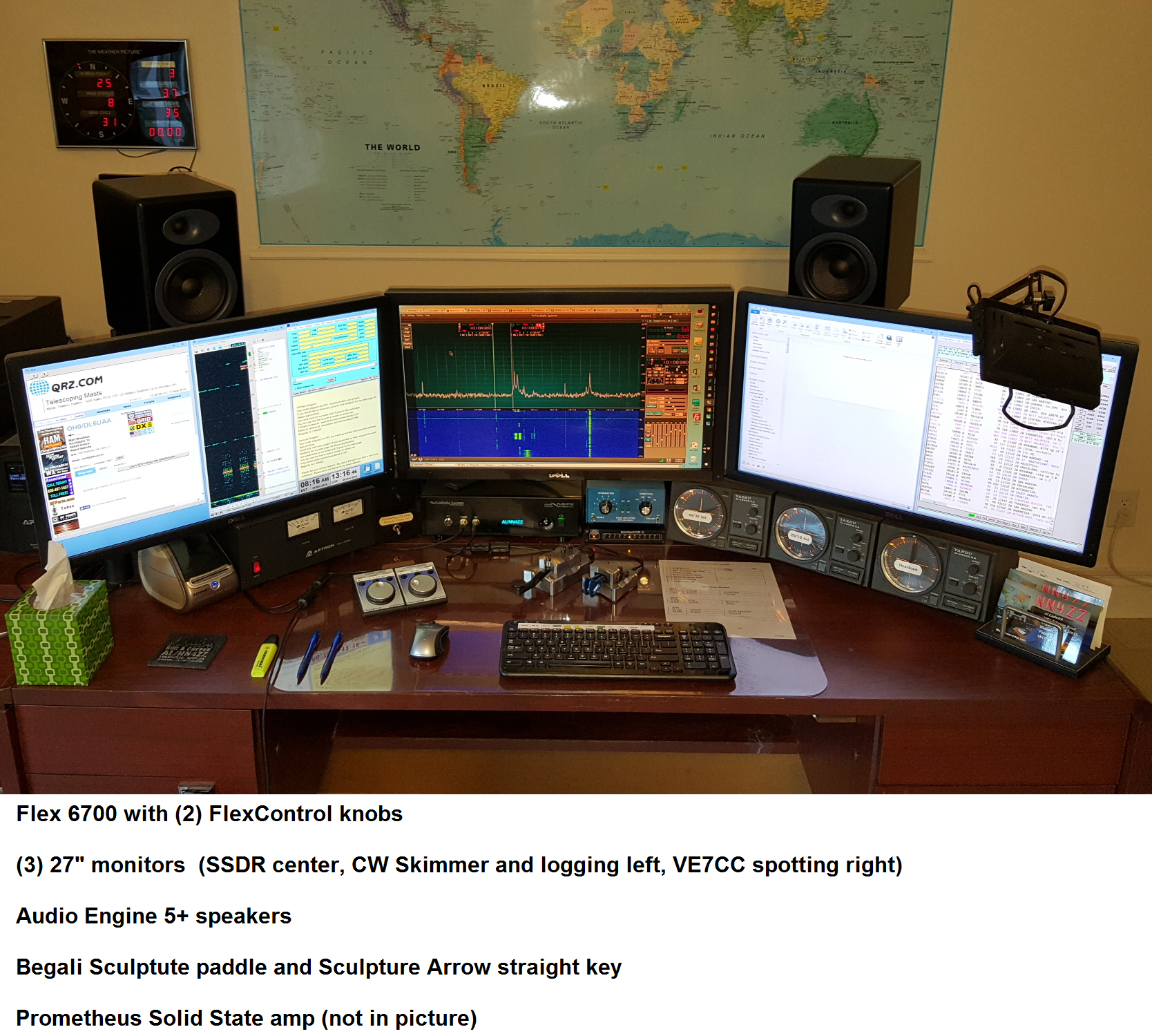
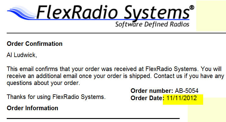
Ordering information (for my 6700)
Setup - interfacing to the rest of the station
FlexControls - setup to run 2 or more
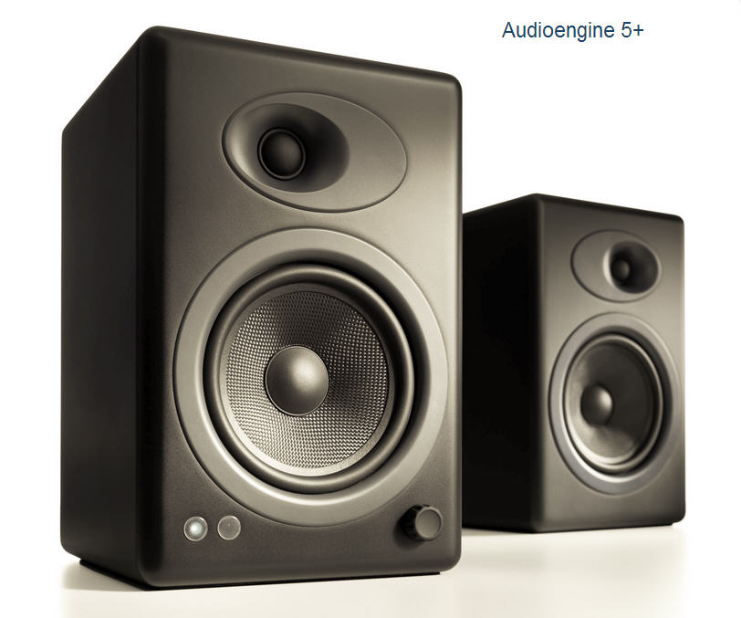
Powered Speakers Audio Engine 5+
Fiber Ethernet connection - RF and Lightning mitigation
USB Port Protection - ESD, power surges and lightning mitigation
Observations ( eHam review )
RF Issues and Solutions - RF ground & Common mode RF
Flex Fans - number and replacements
Low Voltage Lockup issue and solution
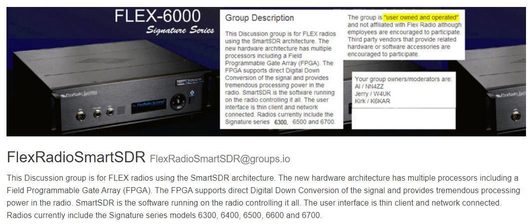
Forum for the FLEX radios on Groups.io - SmartSDR forum
CW Skimmer and SDR-Bridge Setup and Troubleshooting notes 19-Feb-2020
Click here or on the image below to join the FlexRadioSmartSDR Groups.IO forum
Received on 21-Aug-2013
6700 Recall Notice
Notice receive on 25-Sep-2014
3-Nov-2014 - shipped to Austin from Atlanta
6-Nov-2014 - received in Austin
14-Nov-2014 - PEN complete and shipped to Atlanta from Austin
19-Nov-2014 - received in Atlanta
Shack to shack was 16 calendar days, 12 business days.
Station equipment to interface with the 6700
Wiring diagram for the interface between the FLEX 6700, Flex TGXL tuner, Array Solutions Bandmaster III antenna switch and the DX2400 amplifier. USB interface from 6700 starting with V1.10.8
.
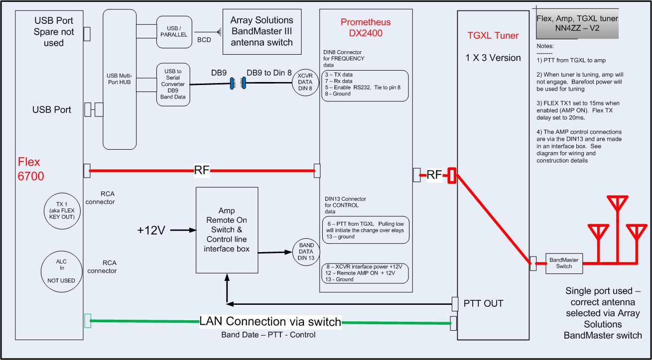
Click here for pictures and more details on the DX2400 interfacing - including the DB9 serial cable for frequency data to the amplifier
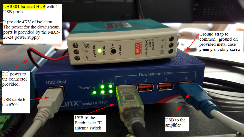
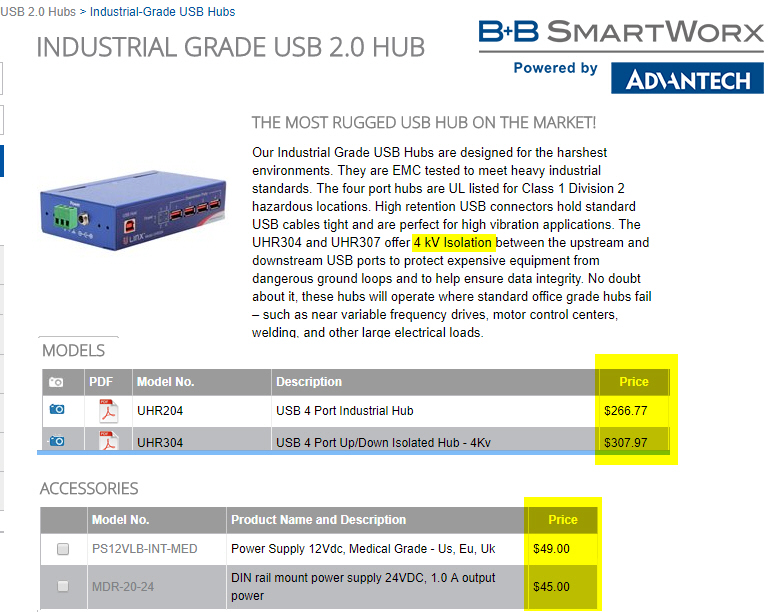
The USB port on the Flex6700 is another place where power surges, ESD, and lightning surges could be an issue. I am using an isloted USB hub to mitigate the chance for damaging the USB radio port.
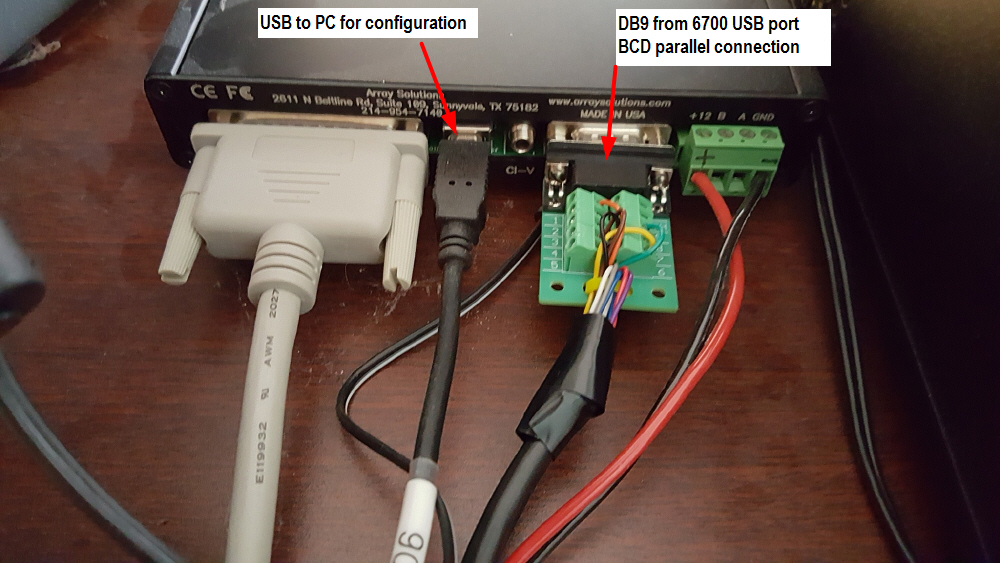
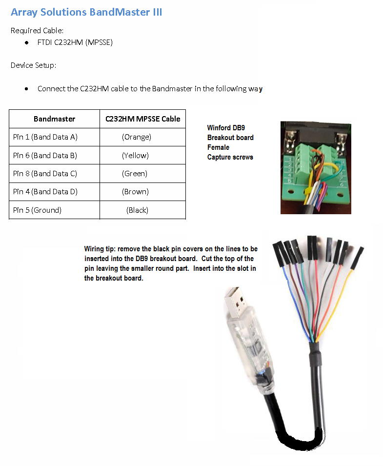
BandMaster III to 6700 USB port (effective with SSDR V1.10 and later) - BCD parallel connection
Cables and setup for the BandMaster and SSDR USB configuration below. Starts with a view of the rear of the BandMaster where the cable plugs in for the frequency data.
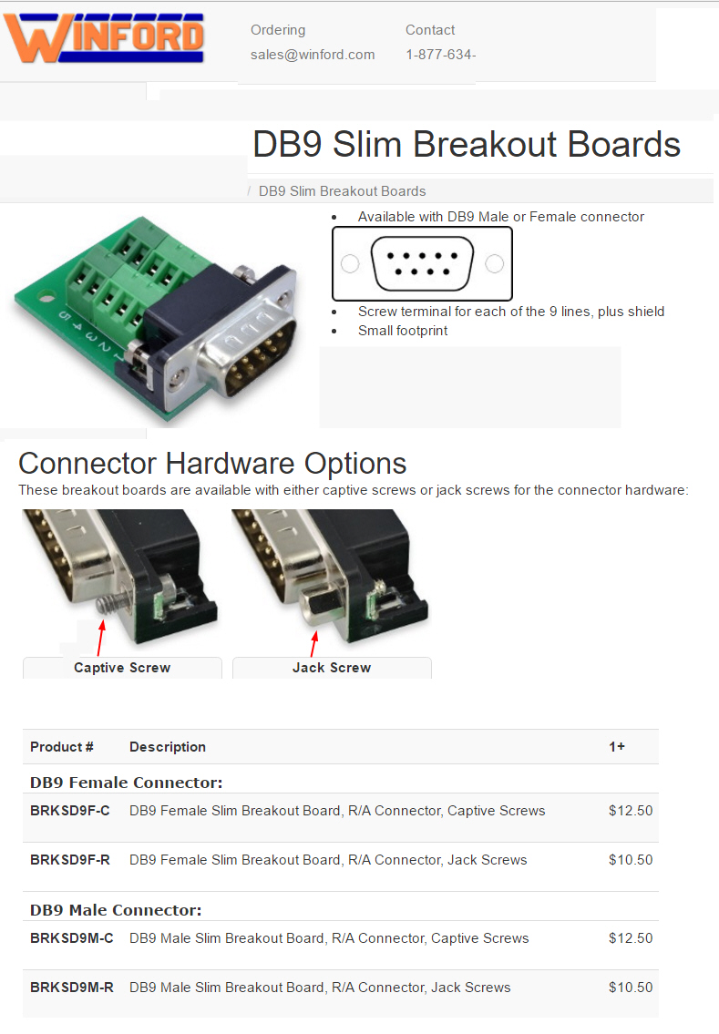
The DB9 FEMALE connector needed is listed and more details on the Winford breakout boards are listed below.
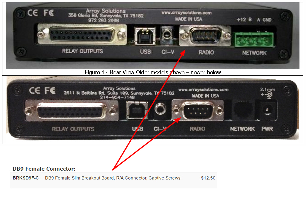
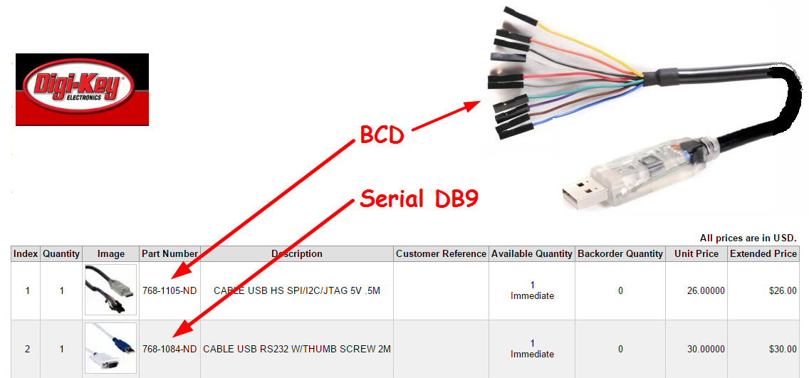
************* Use the BCD cable **************
*************** Uset the BRKSD9F-C breakout board *************
***** Here is the wiring for the DB9 breakboard from the BCD cable. For example the orange wire connects to Pin 1 on the board. *****
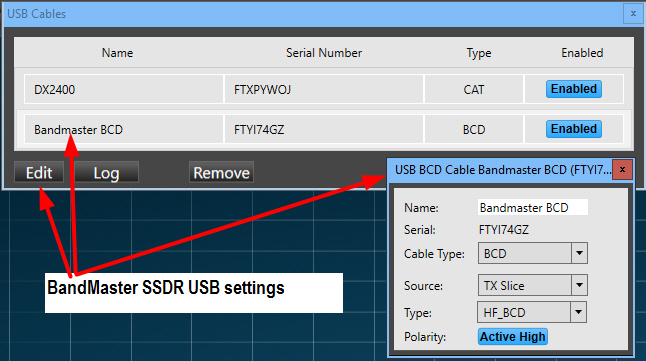
****** Here is the configuration of the USB cable in the SSDR software **********
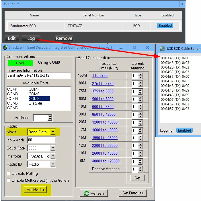
*********** Here is the configuration of the BandMaster **********
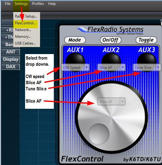
FlexControl setup to use 2 knob with SSDR
There are several ways to setup the software to use 2 (or more) Controls. Since I always have SDR-Bridge running I use it to control one knob and SSDR to control the other one. If you don't use SDR-Bride (or have it running all the time) you can also use DDUtil to control one of the knobs. Below are some screen shots showing the setup for both ways.
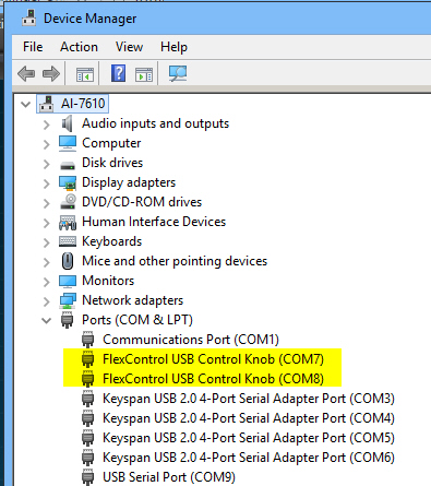
- To start verify that Windows device Manager shows 2 FlexControls
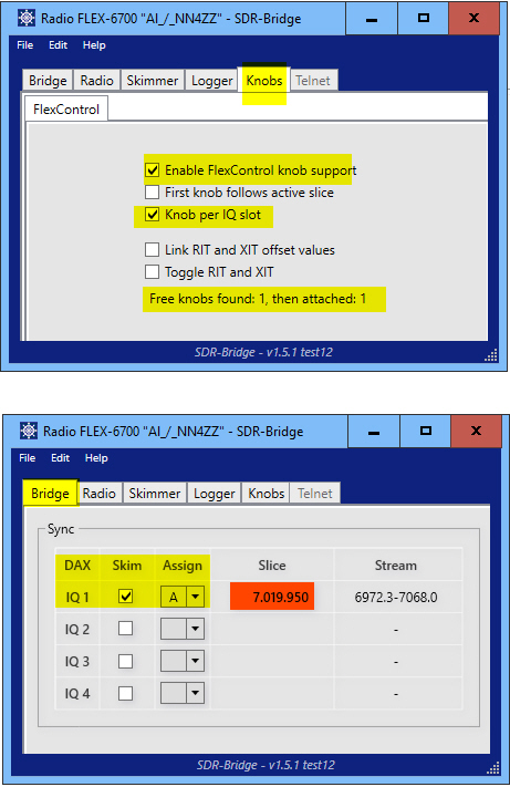
- Now start up SDR-Bridge and configure as below, it will then find and grab the other FlexControl knob.
- Note the message that says “flex knobs found 1, then attached 1.” I have it also set to assign one knob per DAX IQ slot since I always want this knob to control slice A.
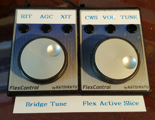
- Note: The SDR-Bridge sets the button functions to RIT, AGC, XIT. You don’t have any control over the button functions.
I put some Dymo stickers on the FlexControl to remind me of the settings.
I leave the PC up 24x7 and also leave the SDR-Bridge program running on my PC 24x7. I do shut down SSDR when the radio is not in use. The setup sticks and I don’t have to go back and do anything when I start up SSDR. The FlexControl knobs stay properly configured. If you shut down your PC regularly, The only thing you have to do is start SSDR first to let it grab it’s knob and then start SDR-Bridge to grab the other one.
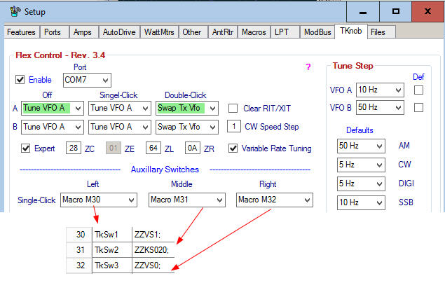
Here is the DDUtil setup if you prefer to use it instead of SDR-Bridge. It actually provides more button capabilities than SDR-Bridge but since I’m already running SDR-Bridge and not DDUtil I went with the solution that required one less program.
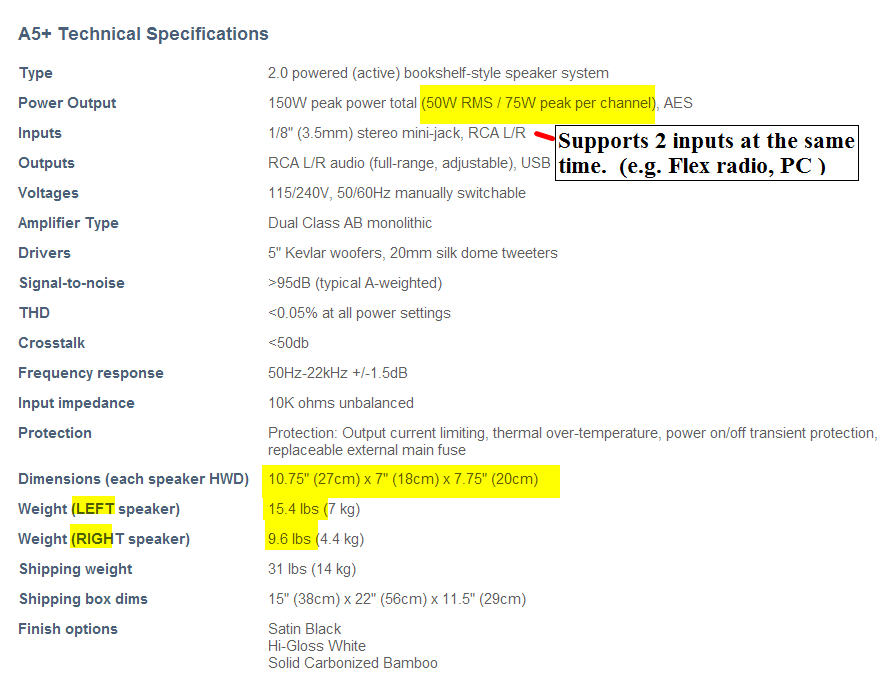
Powered Speakers - AudioEngine 5+
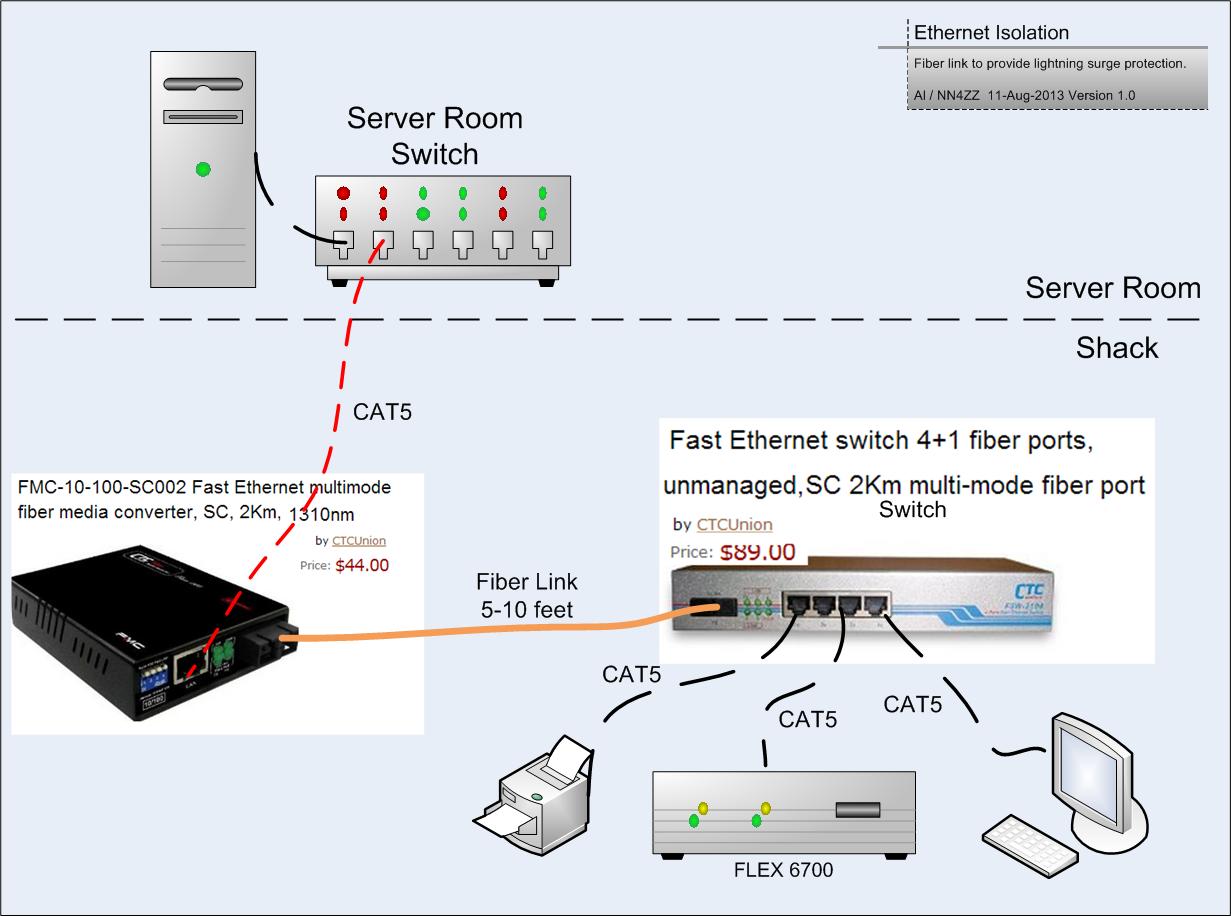
The Ethernet port on the 6700 is a potential weak point for lightning surges. For protection I added a fiber link to electrically isolate the port. Since I also needed some addition ports in the shack, I used a desktop switch with both fiber and CAT5 copper ports.
The problem is long runs of CAT5 cable act link an antenna and a close by lightning strike will induce a voltage spike in the cable. The solution is to isolate the devices you want to protect with a short fiber link near the device. In addition a close by lightning strike can induce spikes into any of the wiring systems (phone, power, cable TV coax, etc) in your house which can jump to your ethernet CAT5 cable.
The install was plug and play and took about 5 minutes. The cost was about $150. If you don't need the extra ports provided by the switch you can use 2 media converters lowering the cost to about $100. Replacing an ethernet interface card in a PC is easy, if the ethernet interface card in your radio is damaged, it will require a trip back to Texas for repairs.
Visit the Groups.io forum for more information on the components and other Ethernet isolation solutions. Look in the FILES section for the Ethernet Lightning protection folder.
Ethernet to fiber converter
Orange fiber cable - note A & B designations
Grey CAT5 from server room
Switch settings -- all UP
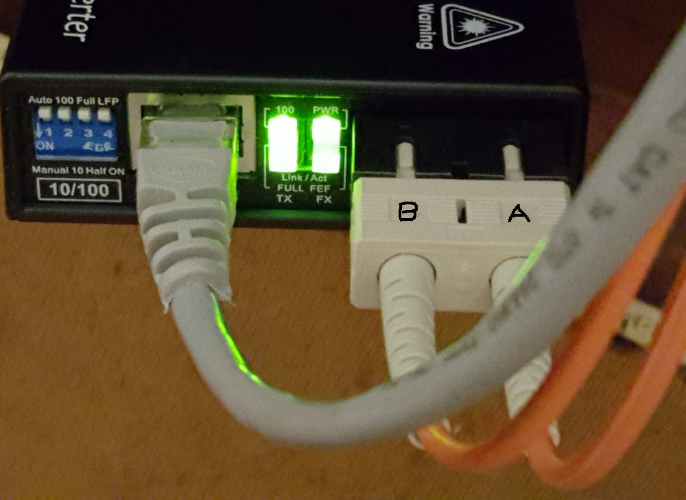
Fiber Cable -- MultiMode
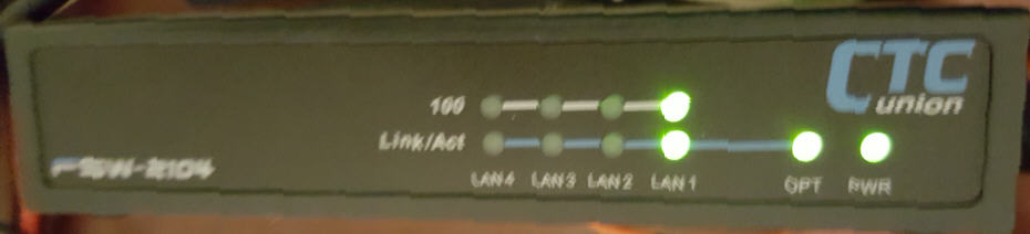
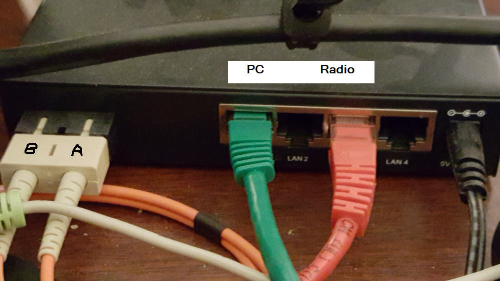
Switch picture - front and rear
Green CAT5 to the shack PC
Red CAT5 to the 6700
Orange Fiber to the media converter - Note A & B designations

For more information
Click here or on the image below to join the FlexRadioSmartSDR Groups.IO forum
Observations and performance
August 30, 2014 -- My eHam review
|
|||||||||||||||||
I've noticed that my 6700 is more sensitive to RF than my previous radios. I initially had problems with the radio crashing on transmit and reporting false SWR readings on some bands. Often these problems can be remedied with proper RF grounding and RF chokes on the coax and other cables. My station grounding was already in place but will be documented below. The solution for my issues was identified and resolved by addressing the RF on the coax and other cables. Both grounding and RF on the cables is addressed below.
Grounding
Without going into all of the details there are several types of grounds. It's considerd good practice to address all of the grounding strategies in a amateur station. Some say there are 3 types to consider, I list a 4th one here. The RF ground (#2 in the list) is the one that can most affect your radio during normal operation. Grounding is an often debated subject, so take what is presented here for what it is worth. The solutions worked for me but you may have a different experience.
1 - AC safety ground (the third wire in you 120V outlet in the U.S.). This is not an RF ground but as the name implies it is for personal safety against electrical shock.
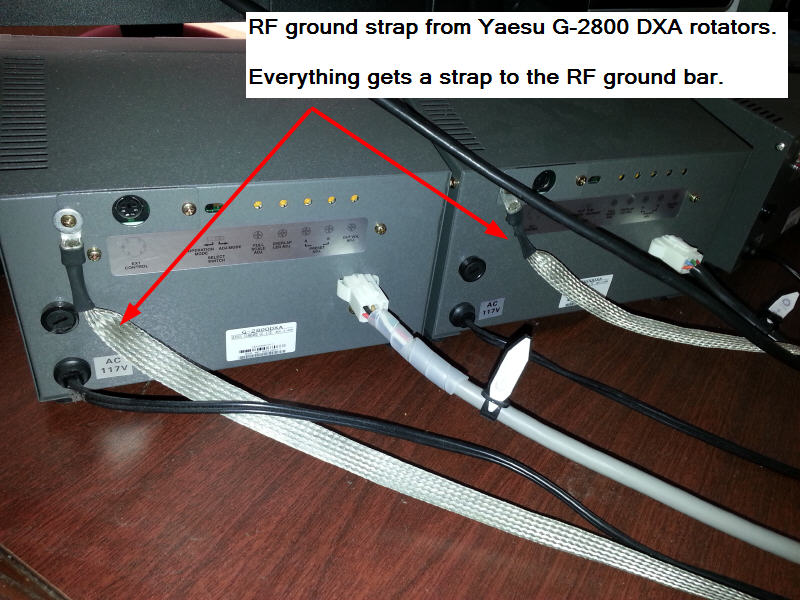
2 - RF ground - provides a path for RF to a common buss bar close to the operating position and connected to a ground rod close by for all of the "boxes" at your operating position. This is not the same as the AC safety ground. Lack of a good RF ground can introduce ground loops and significantly impact you normal radio operation.
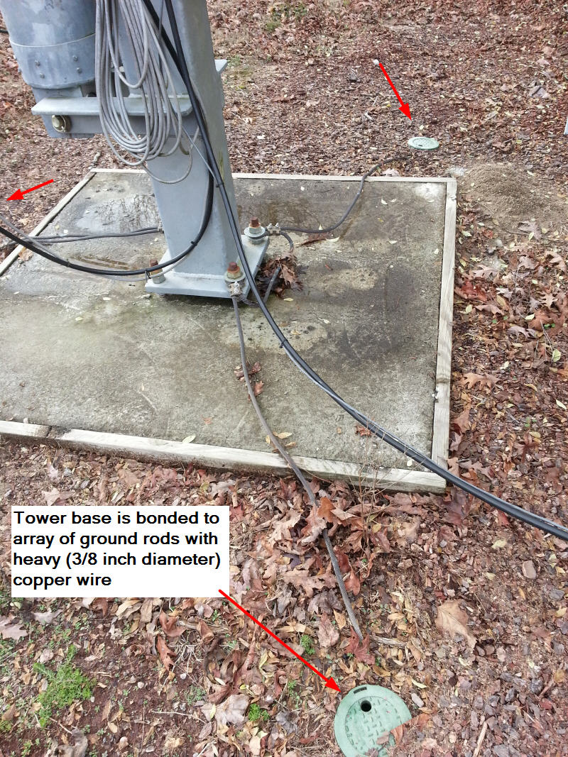
3 - Tower ground - lightning protection for each tower to an array of ground rods around your towers
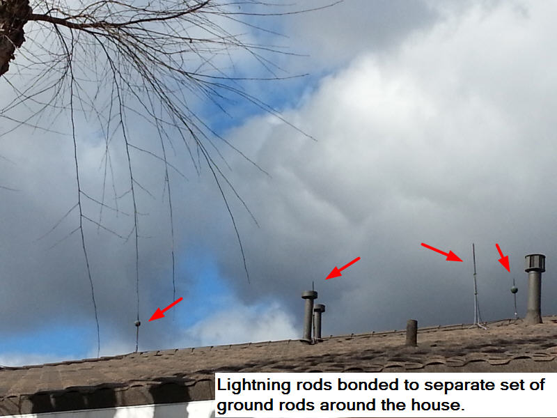
4 - Dwelling lightning protection - If you live in a lightning prone area you may want to also consider installing lightning rods on your dwelling. The lightning arials are bonded to another set of ground rods around the dwelling
RF on the coax and other cables
In addition to the RF ground, you may also need to consider common mode RF feedback on you antenna coax. Ideally all of you transmitted RF remains inside the coax and is transferred to your antenna. Unfortunately this is not always the case and you can get some RF feedback on the outside of the coax and back to the station. Even if your coax and antenna are matched, radiated RF can be picked up on the coax shield. This unwanted RF is typically mitigated with a choke or ferrites at the antenna feedpoint and/or where the coax enters the shack. The results of unwanted RF in the shack can be manifest in a number of ways. Here are a few.
- RF burns
- Radio lockups ( I noticed my 6700 to be more sensitive to RF than my other radios and had this problem)
- PC lockups
- hum or noise in your audio (speakers, etc)
- false trigger on fire alarms, touch lights, etc
- False SWR readings
There are many good documents on RF chokes and common mode. Click Here for additional background.
Howard / KY6LA has put together a good presentation on "how to build a quiet station" that is also a good reference. Clike here for the presentation
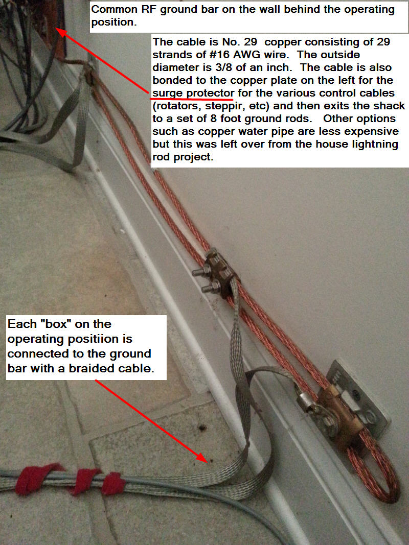
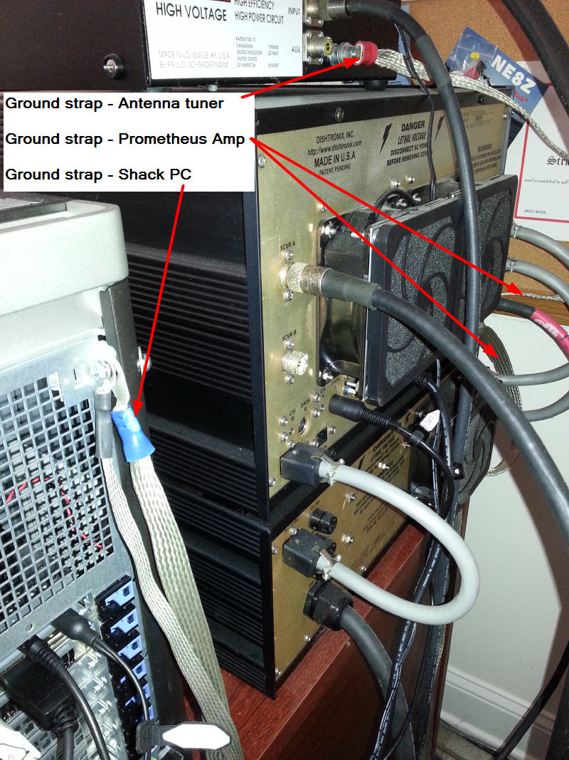
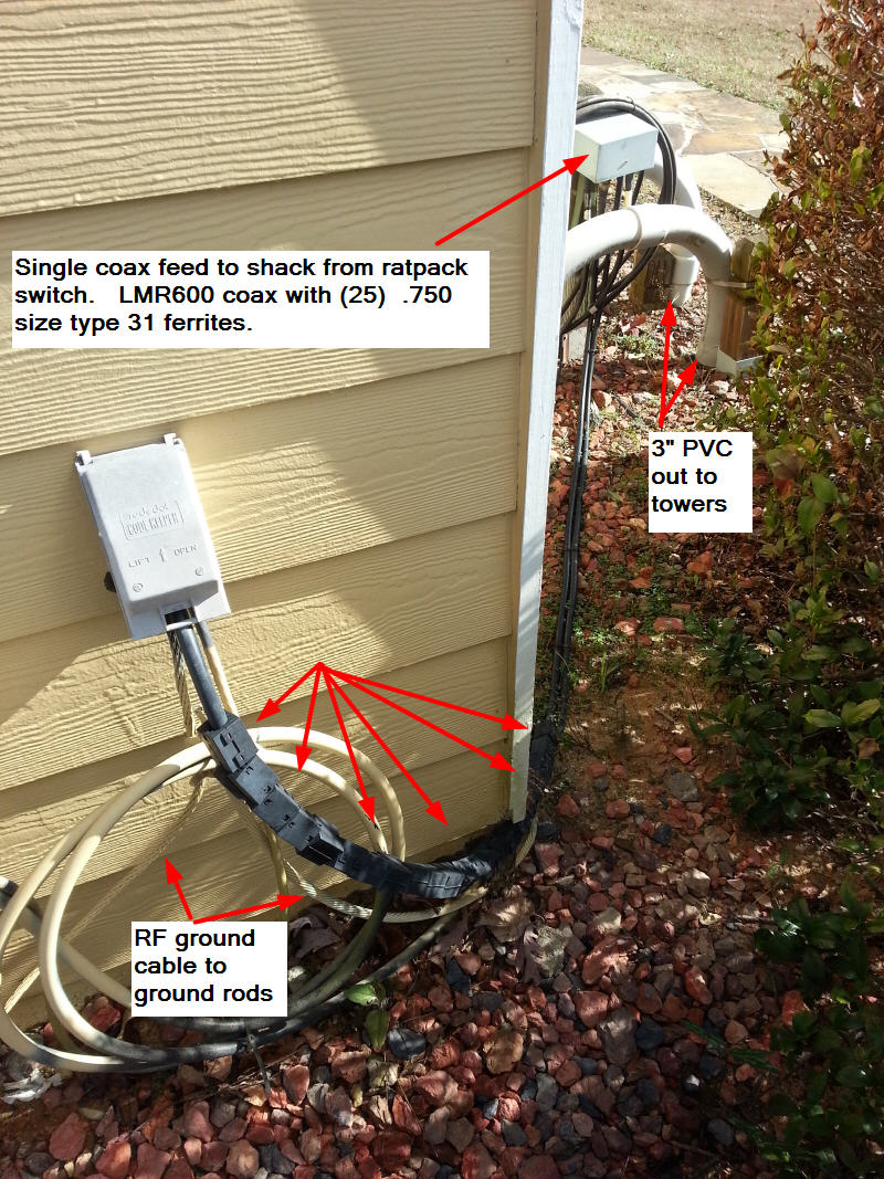
RF grounds
Here are some pictures showing my RF ground setup. Every "box" at the operationg position gets a ground strap. Some of them are shown below
Tower grounds
The idea is to provide a path to ground for any lighting strikes to the tower. This won't eliminate the possibility of a surge on your coax or control cables but it should help reduce it and is a first line of defense.
Lighting Rods -- installed on the house.
Harger.com is a good source for lightning protections products. If you live in a lightning prone area you may want to consider this. In addition to reducing the potential for equipment damage it could also prevent a fire. House fires from lightning happen at least once a year in our area.

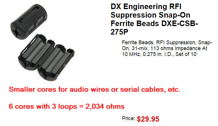
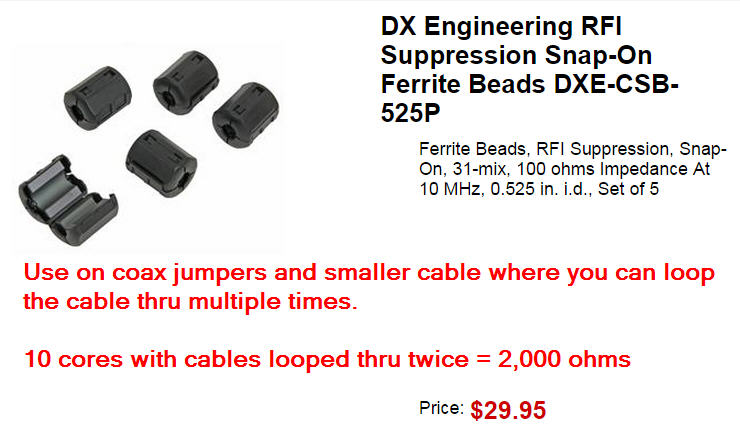
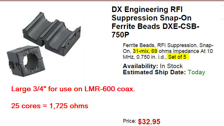
RF choke for common mode
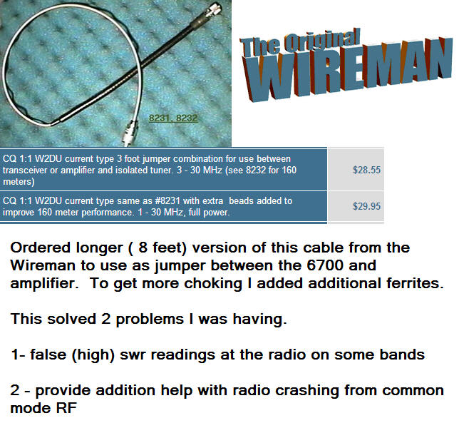
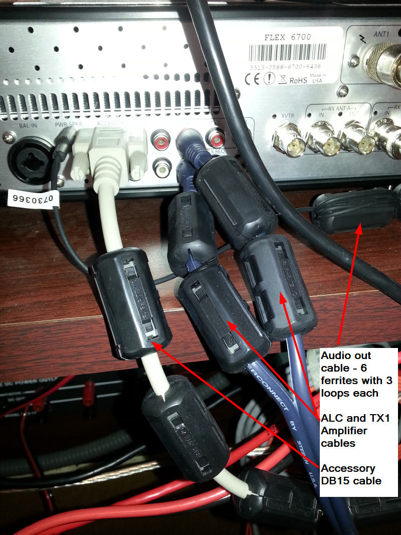
Here is some information on the ferrites I use from DX Engineering. Also the pictures show how I used them on practically all of the cables in and out of the 6700. I was having a problem where the 6700 would occassionly crash when I tapped the key in CW and it was much more frequent when using the amplifier. My strategy was to add ferrites to one cable at a time to see what had the biggest impact in correcting the problem. There were 2 area where adding ferrites had the biggest impact. Adding ferrites to the coax coming into the shack and also on the coax jumper between the 6700 and the amplifier. All of the other places I added ferrites have only a small if any effect but since it never hurts I've left them in place.
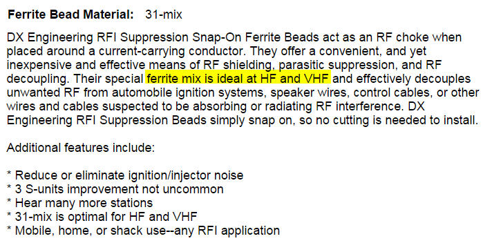
Most of the ferrites in the shack pictures below are one of the 3 sizes shown here.
Coax leading into the shack was one of the two places that had a big impact
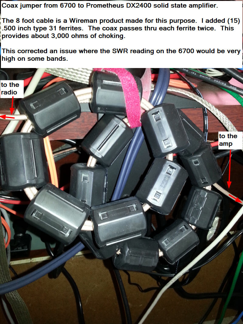
The coax jumper between the 6700 and my amplifier is the other place that had a big effect.
The picture below shows two coax loops hanging on the back of the desk.
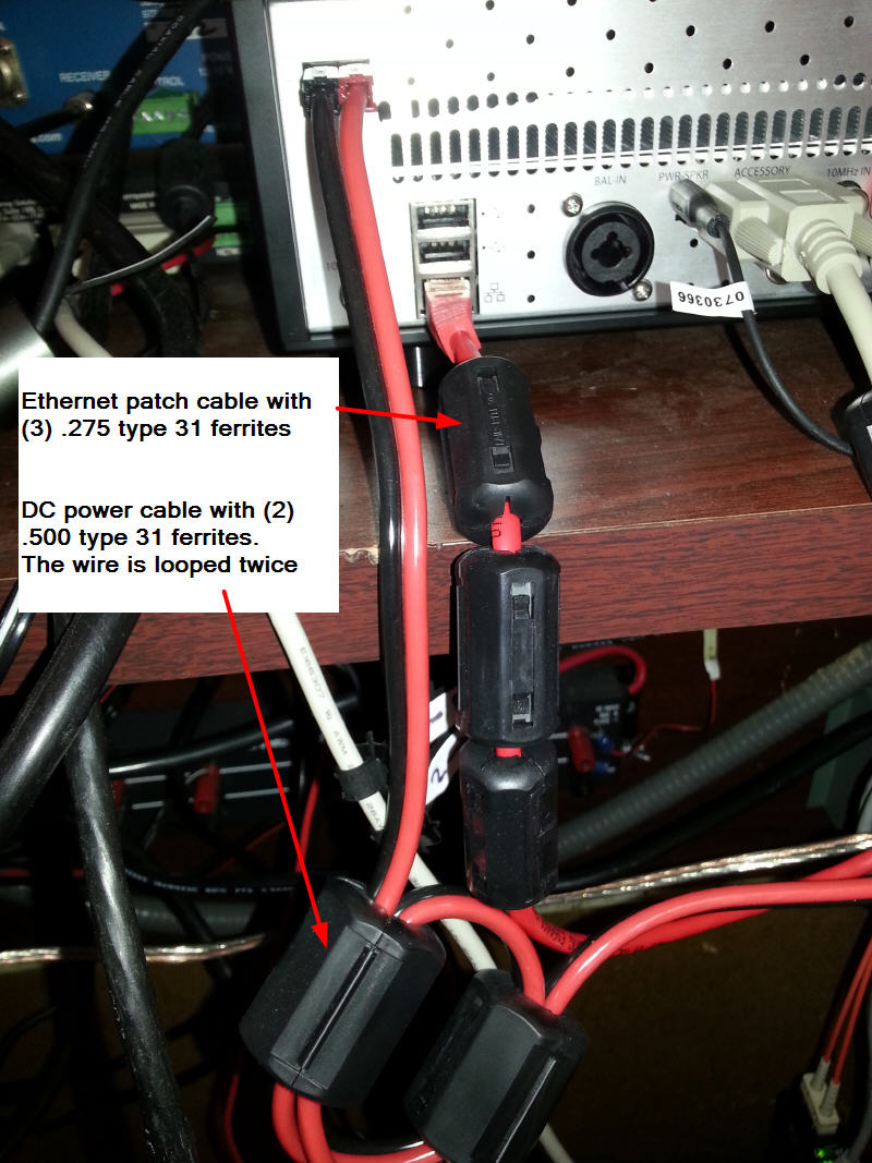
I added ferrites on all of the other cables also......
Note about the ethernet connection: I also implemented a fiber link for the ethernet connection. This is documented previously on the web page. Although it was added for another reason, it also helps with RF mitigation.
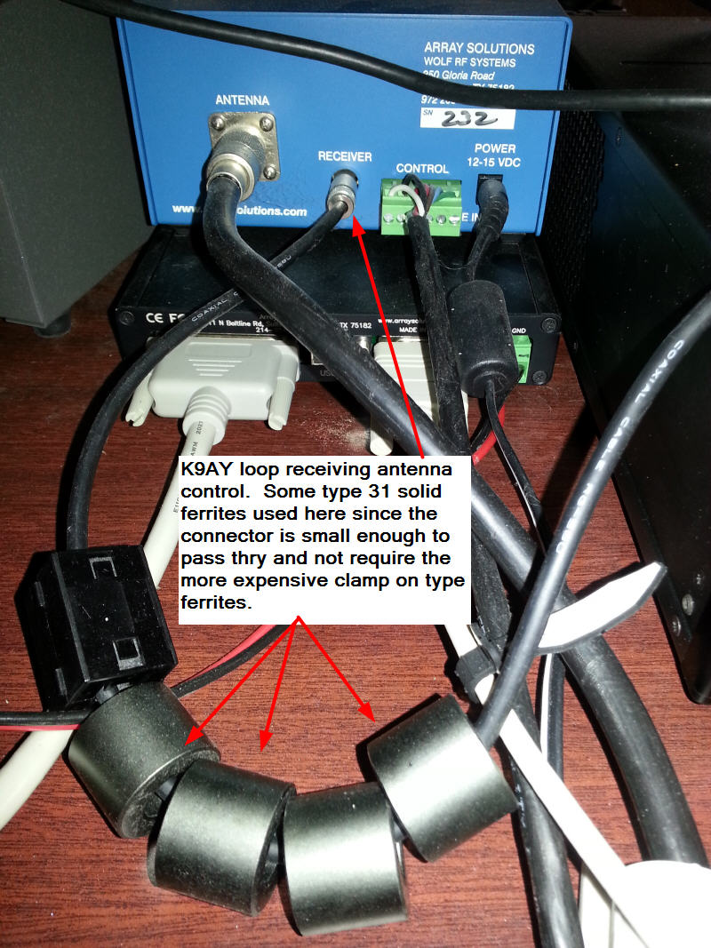
In additon to a number of transmitting antennas, I have a K9AY loop for receving that I use on 80M.
For more information
Click here or on the image below to join the FlexRadioSmartSDR Groups.IO forum
Flex FANs
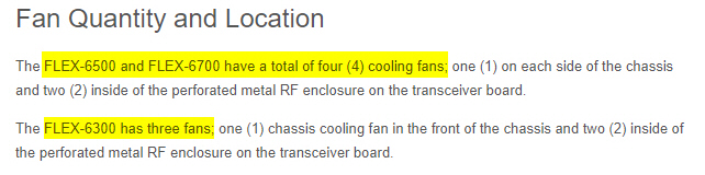
There has been some concern about the failure rate for the fans in the 6300, 6500, and 6700 radios. Some of the 50MM fan failures have occured within a year and others have been running for 5+ years. The first sign of a failure can be an error that prevents the radio from operating. FRS recommends returning the radio to the factory to replace the fans. The turnaround time may be an issue for some so several hams have put together information on the parts and process to replace the fans in the field. The case fans are easy to replace and readily available. The CPU and FPGA 50MM fans are under an RF cage. In addition the ORIGINAL 50MM fans are not as available in small quantities. However they can be replaced by the user in the field. More details on all of this below. Thanks to Eric/K2CB, Manuel/W4SSB, Dave/WO2X, Bill / W2PKY, Kent / N6WT and others for their input and help.
NOTE on the 50MM FANS : FRS changed to a new style 50MM fan/heatsink in mid 2018. The parts and replacement information below for the 50MM fans will show both the ORIGINAL and NEW models. To change from the old style to the new style, the heatsink must be removed from the CPU and FPGA. It is attached with a strong thermal adhesive and if not removed correctly, it can be really easy to pull the solder balls away from the PCB. Changing from the old style fan/heatsink to the new style is something that you would probably want to have done by FRS. Once the heatsink is in place, replacing the fan on either style is a user serviceable option.
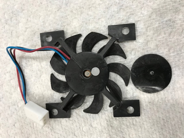
The OLD STYLE 50MM FAN -- may be oiled to provide relief - Picture below provided by Bill / W2PKY
Depending of the failure reason, you may be able to restore operation by applying a drop of light weight oil to the 50MM CPU / FPGA fan bearing. Teflon oiler pen or 3 in 1 oil suggested. To access the bearing remove the small sticker on the back side of the fan.
On the bottom side of the fan is a black sticker that can be peeled off with your finger nail or Xacto knife. The fan shaft is exposed and can be lubricated with a small drop of light oil. I removed the retainer ring using a sharp knife to allow the blade assembly to be removed from the body. The shaft can be cleaned and lubrication can be applied to the bearing. Replace the Teflon spacer and use black electrical tape in place of the sticker. Run the fan on the bench for a few hours to be sure it will be reliable in the radio
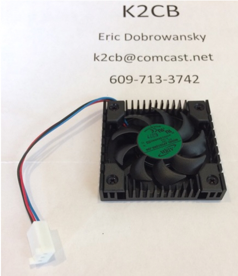
This picture shows both the ORIGINAL style 50MM fan and the 80MM fan.
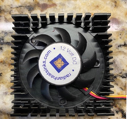
Here is a picture of the NEW 50mm fan.
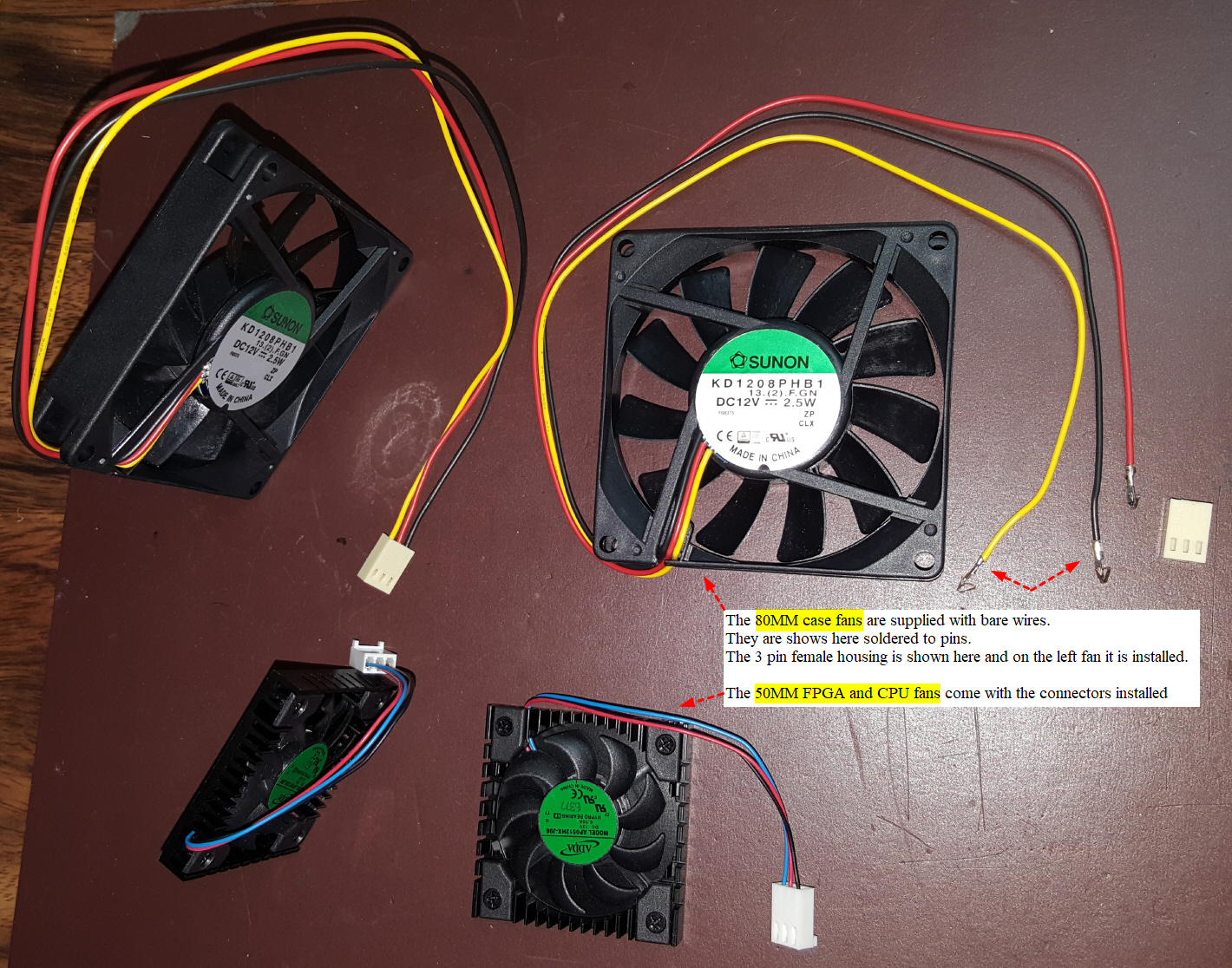
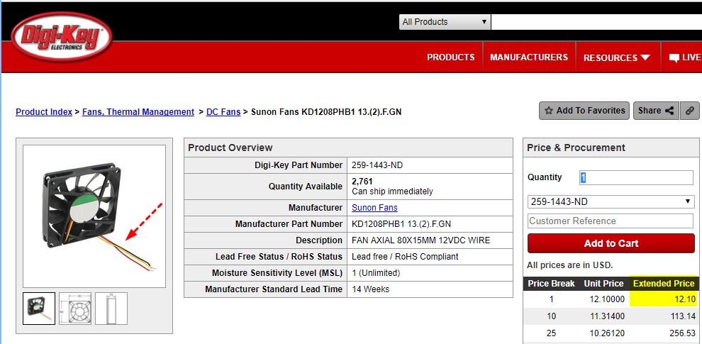
80MM CASE fans
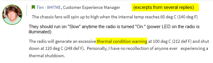
The 80MM Fans are available from DigiKey. The common failure symptoms are a clicking, or whining sound from the fan bearings. There may also be a "high temperature error" displayed on the SSDR client. This seems to be rare and I haven't seen any reports with the exact error message. These fans are easy to replace and don't require removing the RF cage.
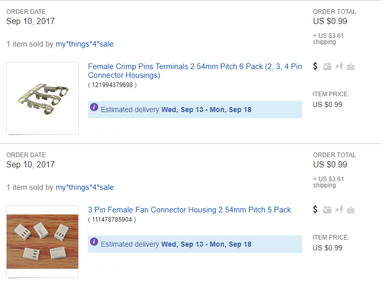
Connectors and pins available from eBay (thanks to Dave/WO2X for this info)
The pins come on a strip, just bend back and forth to detach them. The wires are already tinned, crimp them in the pins with the tabs and solder. The pins slide into the connector and have small tabs that snap in place.
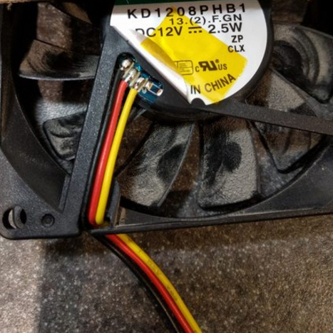
If you don't want to install a connector there are 2 other options. Jim/K6QE suggested you could cut and splice in the old connecor cable. Cut the wiresto the fan, strip back the insulation, add the new fans, and tack solder the wires back. Use black tape or heat shrink to insulate the exposed solder connections.
Another option is to remove (unsolder) the cable with the connector from the old fan and use it on the new fan. My preference is to add the new connector to the new fan but either way works.
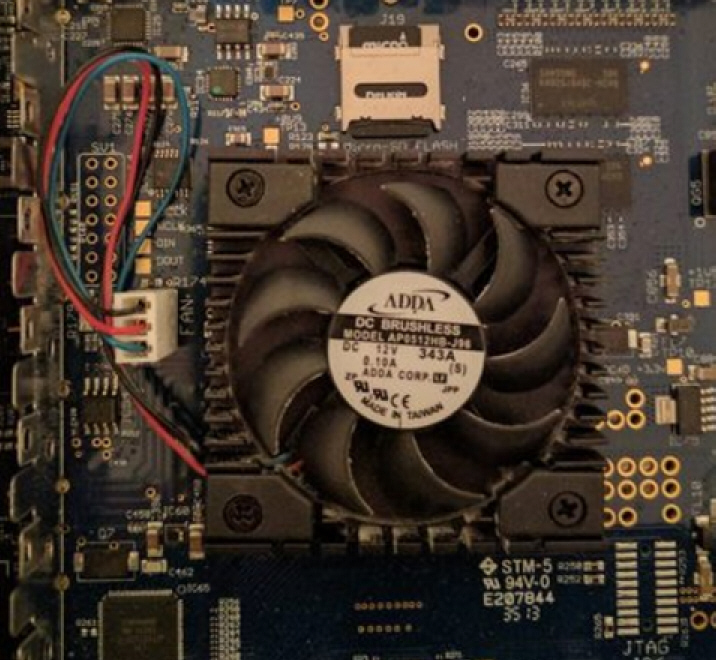
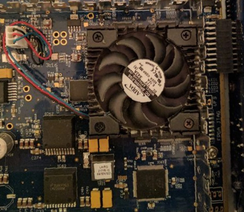
50MM CPU and FPGA Fans
The 50MM CPU and FPGA fans are located under an RF cage. The ORIGINAL 50MM fans are harder to find in small quantities. Eric ordered 100 for a group of us and may do that again in the future.
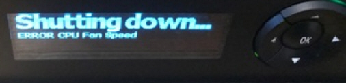
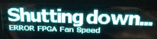
If they fail here are the errors you will see these errors on the radio display for the 6500 & 6700. The 6300 does not have a display on the front of the radio. User feedback indicates that the 6300 just shuts down and there is no error when powering up the radio. You can't tell if the reason for the shutdown is due to the fan error or some other cause.
Also if you are operating a 6500 or 6700 remote you won't get the error message either unless you have someone that can check the front display on the radio.
*** CPU ***
*** FPGA *** (fpga is marked on the board if you look close on the right edge)
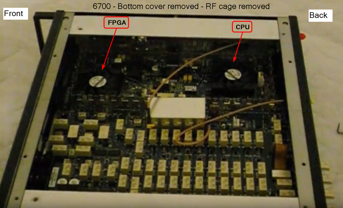
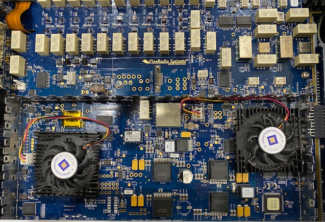
Location of the two fans, most people will want to change both fans while you have the radio open but this will help you identify which one was failing based on the error message on the front panel.
Here is a link to a video by Manuel / W4SSB showing the process to replace the 50MM CPU and FPGA fans.
![]()
The hook tool Manuel recommends to remove the cage is available from Amazon or Harbor Freight.

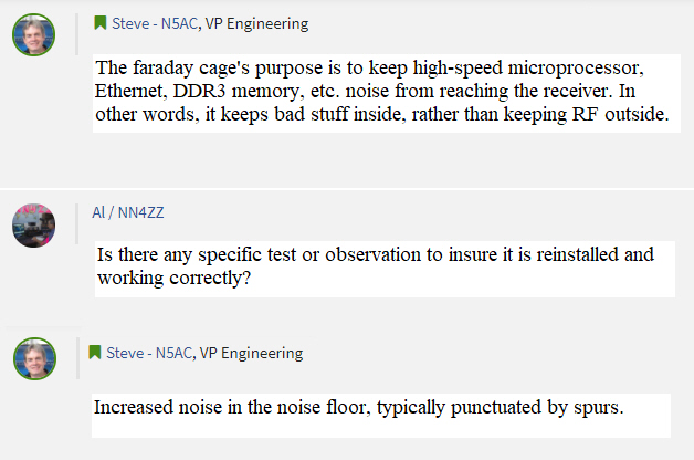
Here are some notes about re-installing the RF Cage and how you can test to verify it is installed correctly. The idea is to take a snapshot of the noise floor without the antenna connected before and after. If not installed properly there would be an increase in the noise floor and spurs. Excerpts below...
Here is another option for replacing the 50MM fan on the OLD Style BLACK heatsink -- Added on 20-Jan-2021
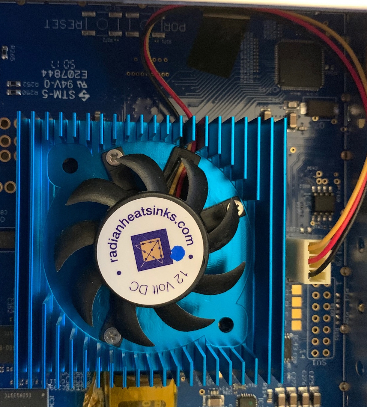
If you don't have a spare OLD style fan and can't get one or would just prefer to use the new "Radiant" brand fan, here is an option you may want to consider. BTW, the new radiant fan is rated for 50K hours or 5.7 years running 24X7. This suggestion, notes and modification below provided by Bill / W2PKY. He updated his fans on 19-Jan-2021.
NOTE: If you send in your older radio with the OLD style heatsink to Flex for a fan repair , they will remove the old fan and heatsink and replace it with the new radiant fan and new BLUE heatsink. This is not something to DIY. Removing the heatsink from the chip is difficult and potentially damaging, I would expect even the Flex techs have to be very careful to avoid damage to the chip and board. Replacing just the fan yourself is generally a quick process ( a few hours) and can save the downtime of shipping and repair.
The "radiant" fans can be purchased for $23 each at the radiant web site noted earlier. The bolt pattern is not the same as the original OLD fan so it can't be bolted in place oin the OLD balck heatsink. Bill used Gorilla clear mounting tape (doublesided) to attach the new radiant fan to the OLD black heatsink. It appears that the tape will hold and the heat from the heatsink will not be a problem. If anyone reports issues I'll update this information.
New Radiant Fan on the OLD style heatsink
Both 50MM Fans updated
For more information
Click here or on the image below to join the FlexRadioSmartSDR Groups.IO forum
After my 6700 was about 6 years old, it started locking up occasionally while
transmitting ( CW ) with a voltage error on the front panel. It was only once
every week or two but got worse and was happening daily... The lockup
would occur when the RF power slider was set to 75+ watts. It
happened frequently when the key was closed and would immediately lock. .
It would not occur at lower RF power settings (e.g 50W). Here is the error
message:
13v8 - 9.44 volts
Check Fuse
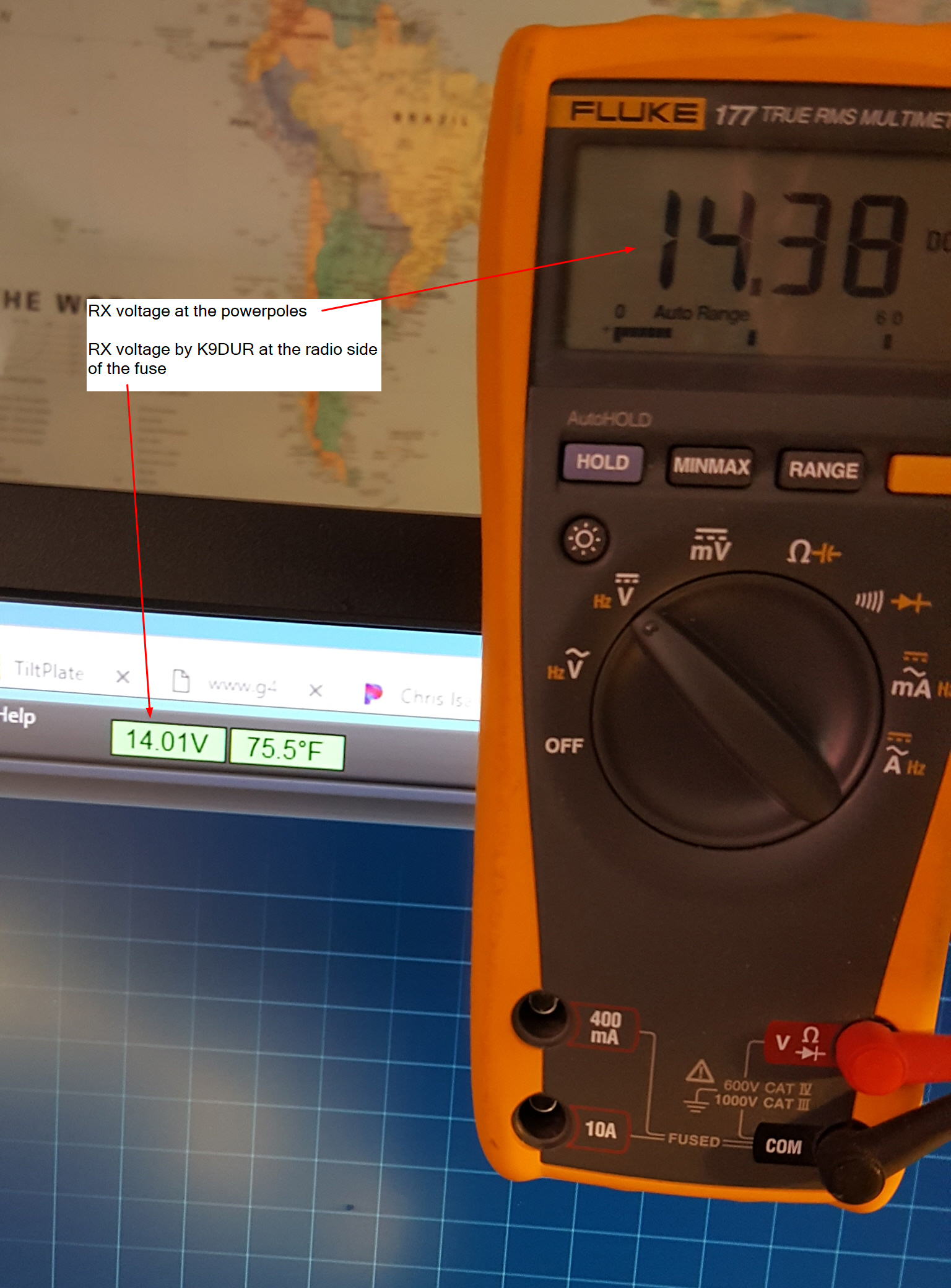
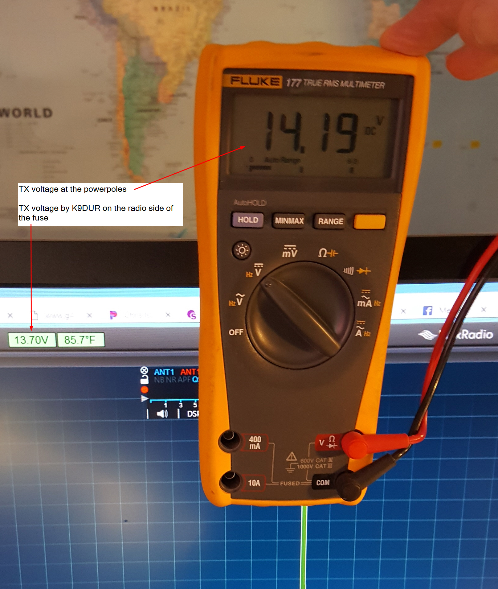
I'm using a linear Astron RS-35M supply and heavy 10 gauge cables to the radio.
The voltage at the rear of the supply was 13.8V and at the radio it would read slightly
lower at about 13.7V.
Using the K9DUR SDRMonitor, the readings on the radio side of the fuse were
13.3V on RX and 12.7V on TX. The measurements were taken with RF output
settings of 80W - 90W. This was measured at a setting of the RF output
slider below the maximum setting of 100W since if the radio locks up
SDRMonitor won't get a reading. So the drop between what is supplied at
the powerpoles and what the SDRMonitor reads was .4V on RX and 1.0V on TX.
The drop between the powerpole and SDRMonitor at TX is
about 1.0V.
From the feedback I've gotten from others, this drop
is a little higher than expected.
If anyone needs
the steps to adjust the Astron RS-35M supply voltage I found a good document on
it by W1MIK.
http://www.repeater-builder.com/astron/voltage-adjust/voltage-adjust.html
CLICK here for more details and the feedback from others about this issue posted in the Groups.io fourm for Flex Radio Smart SDR
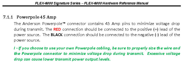
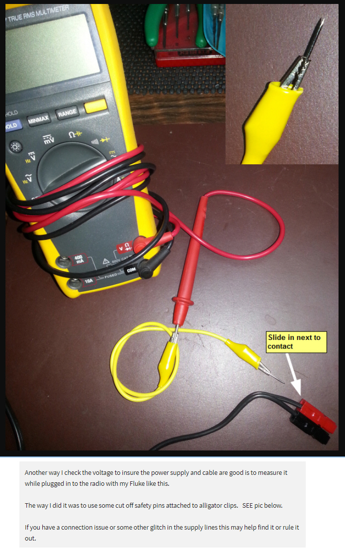
The voltage on the input side of the radio can be measured at the powerpole connectors using the setup below.. If the cables from the supply are short and the guage of the cables is good ( sugggest 10 guage) then the drop from the supply to the radio should be minimal. ( around .1 V).
The snapshots below are form the INITIAL adjustments on the RS35M power supply. As noted above the power supply voltage was adjusted up to 15V on 21-Jan-2020.
Here are some side by sided measurments of the voltage before and after the FUSE for RX and TX.
For more information
Click here or on the image below to join the FlexRadioSmartSDR Groups.IO forum