
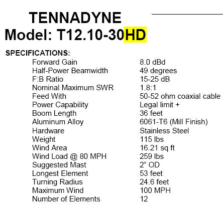
Modification for the NEW Tennadyne HD models T10, T12 and T14 10-30 HD,
(Note: the T14 model can be supported with either the Standard or Monster Tiltplates)
The NEW HD models use a larger BMI (Boom Mast Interface, aka boom mast plate) than the older models without the HD designation. Click here if you have one of the the older models without the HD designation.
The TiltPlate will be modified and the additional hardware provided when you order. The holes will be drilled and ready to mount the BMI when you receive the TiltPlate. The diagrams below showing the drill locations are for reference. You can use either the stackable or non-stackable versions depending on whether you want to mount another antenna above the T12. The optional KARLock is also supported. There is no additional charge for the the TiltPlate modification and necessary hardware.
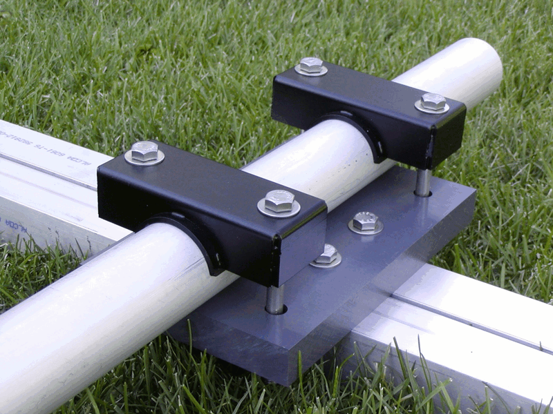
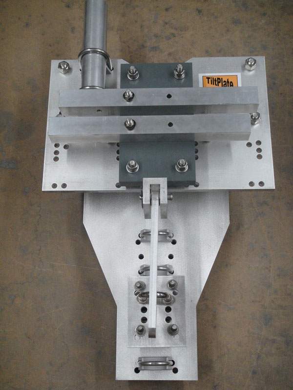
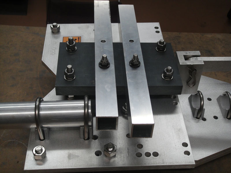
This antenna uses a "dual square tube" boom shown below. The booms are electrically isolated at the boom mast plate with an insulator (the BMI). The booms are attached to the BMI with 3/8 inch bolts. In the normal installation, the mast (round tube in the picture below) is attached to the BMI with 2 clamps.
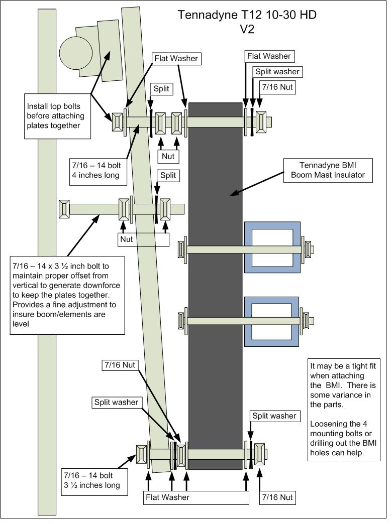
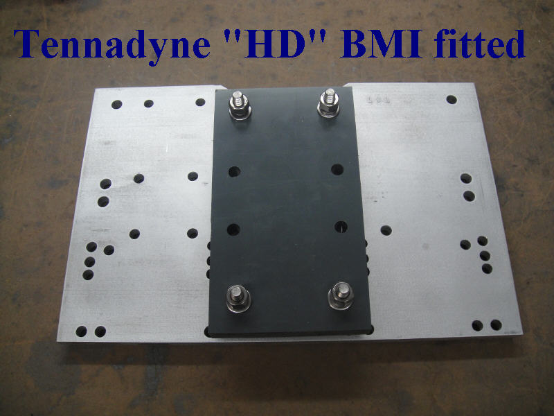
TiltPlate modifications - The BMI is mounted directly to the moveable plate on the TiltPlate with four (4) studs. The TiltPlate BMI studs are 7/16 inch stainless steel to provide a very strong connection. All of the necessary hardware is provided. The optional KARLock can be used with the Tennadyne antenna if desired. Below is a diagram of the BMI to TiltPlate connection.
Note: the mast plate on the TiltPlate and the BMI will be parallel when shipped. No additional antenna leveling should be required to insure the antenna elements are horizontal when the tower is in the operational position.
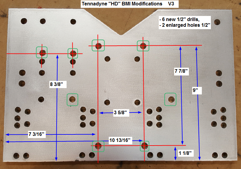
The TiltPlate boom plate is modified to add the mounting studs. Four 1/2 inch holes are drilled for the 7/16 inch stainless steel studs.
2 existing holes are enlarged
V3 shows boom truss mounting holes re-located moved up slightly
The BMI is mounted using the hardware (washers, lock washers, nuts as noted in the "Tennadyne adapter diagram" above.
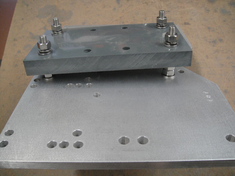
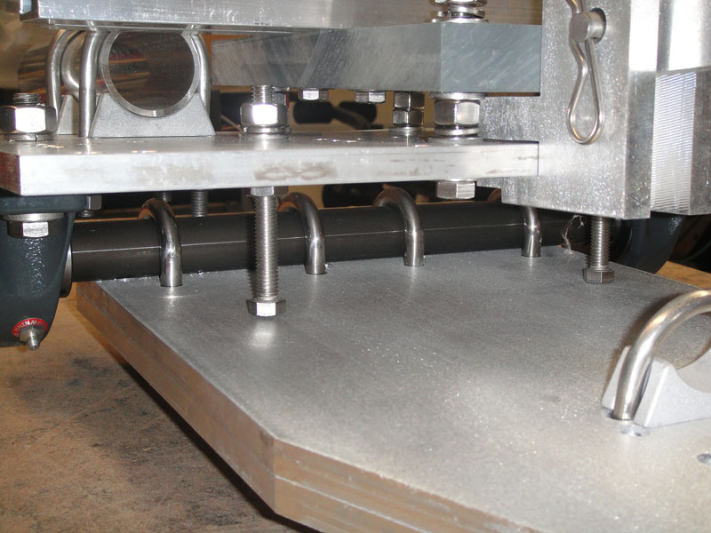
Side view below. The distance between the bottom of the BMI and the TiltPlate is 3/4 inch. The distance between the top of the BMI and the TiltPlate is 1 1/8 inch. The 3/8 inch difference allows for the needed offset.
Assembled and shown with optional KARLock. Sample BMI with short boom sections shown.
Right Side View
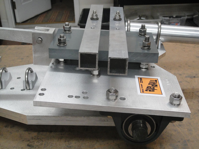
Left side view
View between the plates, leveling bolts shown.
Basic Installation steps
- Install the TiltPlate on your tower. (with the tower in the tilted over maintenance position)
- If you ordered the optional KARLock, install the pivot block before installing the BMI if not already installed.
- Slide the BMI over the TiltPlate mounting studs (the boom sections should already be attached and the antenna may be completely assembled). If the BMI does not slide over the studs easily, you can loosen one or more of the studs to align them. Also drilling slighly larger holes in the BMI is another option.
- Install the hardware (flat washer, lock washer, and nuts) per the diagram.
- If you ordered the optional KARLock, install the catch block and adjust per the KARLock instructions. if not already installed.
-Complete any necessary wiring and the tower is ready to raise. The BMI and antenna should not require any additional leveling however there is a leveling bolt should a fine adjustment be needed.