W0PL / Paul -- DB18 Installation Tips
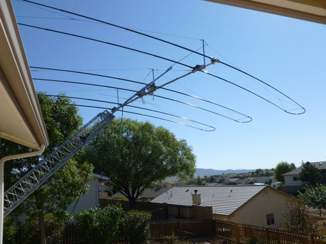
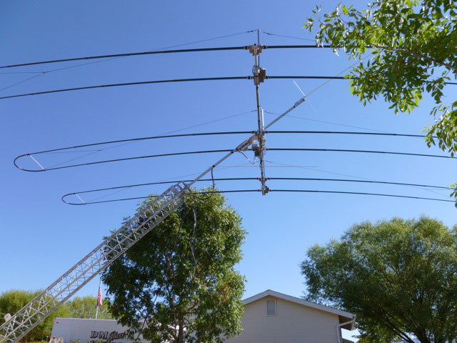
Paul / W0PL provided some installation tips that might be helpful to others who are assembling a DB18E on a TiltPlate. Paul also has the KARLock option.
Click on the links below or scroll down for more information and pictures.
1. Tilt the tower to a comfortable (chest-high or lower) position and secure additional support under tower . Position the Tiltplate and KARlock (if ordered) in their operational positions-torque Tiltplate and KARlock adequately;
2. Assemble the DB18E boom (including the boom eye-bolt).....(you will take this out later and replace with a standard hex-bolt) as in the manual, and position the boom in the Tiltplate U-bolts with all boom bolt heads up...just lightly snub the U-bolt nuts for now;
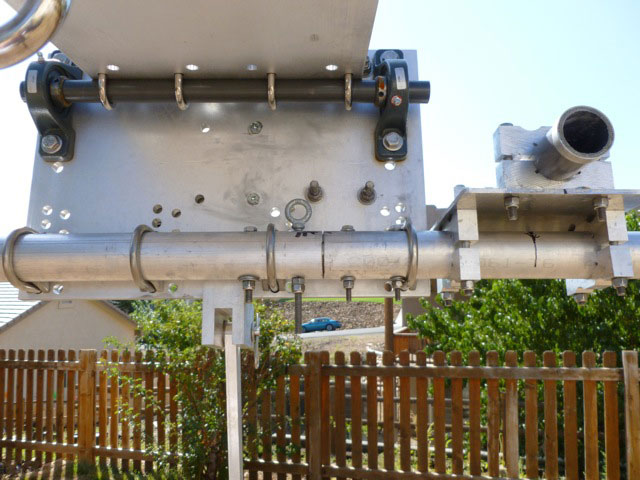
3. You will use (from right side of the Tiltplate to left) the U-bolts in this fashion (to miss the SteppIR boom bolts)...There are (8) U-bolt sets in the Tiltplate.You will use set (1), set (4), set(6), and set (8) to secure the boom;
4. Now, mark the boom for electrical position(s) of the EHU's and EST's....double check all the C/L positions AND the for the proper direction of the motors;
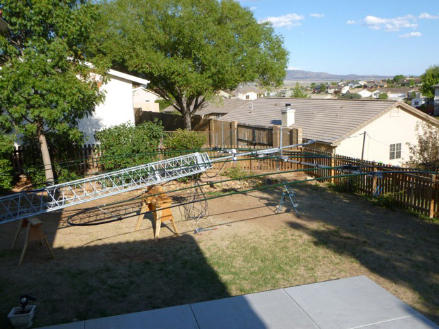
5. Rotate the boom in a right-hand circular fashion until the boom eye-bolt is parallel to the Tiltplate, snub the bolts so the boom is not loose;
6. The reflector end of the boom should be 111 5/16" from the right edge of the Tiltplate and the director end of the boom should be 102 3/4" from the left side of the Tiltplate. Note: The Tiltplate is wider than the factory mast/boom plate;
7. After the wiring of all the motors has taken place....Assemble the director motor EHU in it's proper position AND the reflector EST in it's proper position, rotate as square as possible using the Tiltplate edge as a guide and tighten all director boom clamps and reflector EST hardware;
8. Tie a long string between the director and reflector left tube top sides (not shown)and pull taught... (SteppIR really should provide alignment pins for these devices on the boom-It would solve both rotational alignment issues and electrical position issues);
9. Now, assemble all remaining EHU and EST hardware on their respective marks and rotate the units until you just touch the string;
10. Tighten (torque) all these components and remove string (items should be in rotational alignment and hopefully still on the electrical positioning marks), adjust if necessary and measure again for factory spec's;
11. Remove boom eye-bolt, and replace with 5/16-18 SST hex head bolt and SST washers/nut. Torque securely!
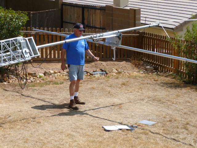
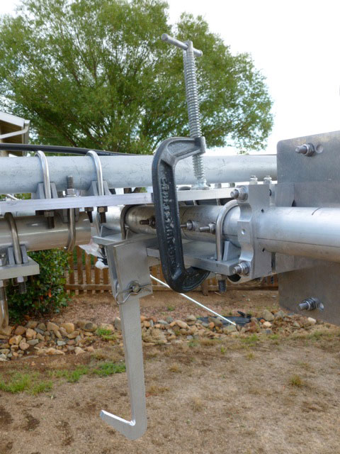
1. Loosen boom U-bolts enough to rotate boom. Rotate Tiltplate until the back of the U-bolts touch the main plate (this is easy to do if one ordered the boom truss option, as you can use the 30 " truss mast as a torque fulcrum) on the mast. "C"-clamp Tiltplate to main plate.
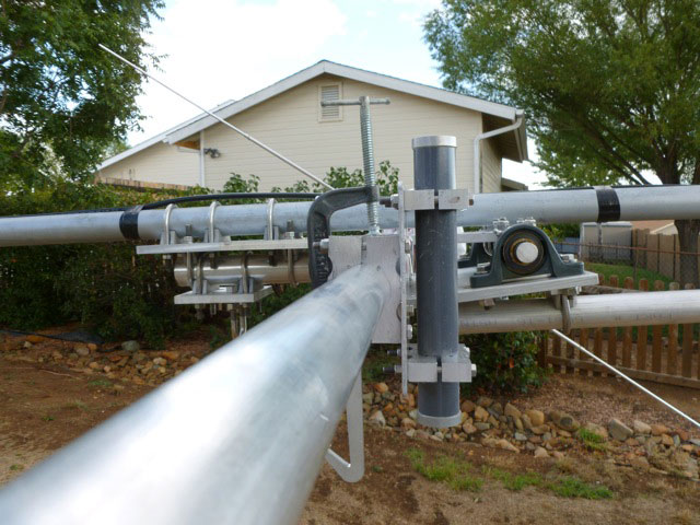
2. Now, using the driven element EST unit, rotate boom until perpendicular to mast. Tighten all boom U-bolts securely! While restraining boom from swinging wildly, remove "C"-clamp and swing down boom. The elements should now be as perpendicular to the mast as possible!
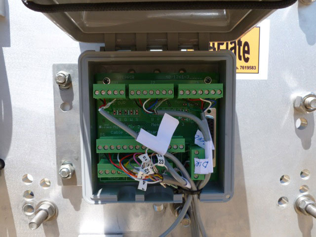
1. SteppIR only provides 240" of control cable. This cable must be cut in half (120") and the connector box should be mounted on two of the center holes provided in the Tiltplate. If this is not done you will not have enough cable to reach the box from one of the end motors.
Make absolutely sure when finished that ALL fasteners are properly torqued! This beam has hundreds of fasteners.
It is a good practice to torque stripe all fasteners with an ink pen then you will know what is torqued and what has not be torqued. Also, it is a good idea to check all Tiltplate fastener torque. It is imperative that you wire the 16 wire cable accordingly to the Addendum provided with the manual for the 25 pin header plug and not the 20 conductor schematic in the manual. It is HIGHLY advisable to order this 25 pin header plug when you order the array...
SteppIR has not updated their manual (as of September 2011) for the DB18E and there is a lot of outdated info in the manual.
.jpg)